1. Go to “Controller Tag”, the data frame is available with all data that is sent from the SME. This is created once you add a new module.
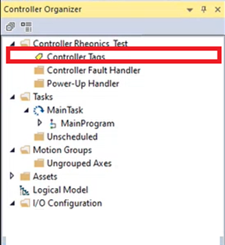
Figure 1. Opening Controller Tags.
2. Rheonics sensors output the measurements which are referred as parameters. The data frame is expressed in Logix Designer as shown below once the Controller Tag is selected.

Figure 2. Data arrays created in Logix Designer.
3. SME index values should appear in the PLC tag array as if it was an Ethernet/IP device and the function block CPS can be used to correctly line up the variables.

Figure 3. CPS function block. Used to match data frame.
4. When done, line-up Data will be available for every application.

Figure 4. Data are shown in PLC tag array
References: