Which Rheonics products are related to this Article?
This Article is based on the use of the SME (Smart Module Electronics) from SRV, SRD, DVP and DVM. Hence it can be used for any of these Rheonics sensors.
What is this Article helpful for?
This article helps with the correct wiring to use SME's 4-20mA Channels and read them correctly with the Allen Bradley's 1798-IE8 Analog Input Modul and similars.
1. SME 4-20mA Channels Overview
Rheonics SME (Smart Module Electronics) has 3 in-built Output Channels for 4-20mA measurements. These are labeled in the SME housing as CH1+, CH2+ and CH3+.
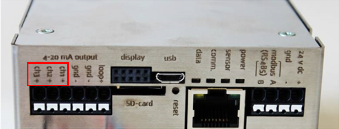
Figure 1: SME Analog Output Channels.
By default, these 3 Channels send the following Parameter for the SRV and SRD sensors.
Channel | Default Measurement SRV |
1 | Viscosity Median and Last Good |
2 | Density Median and Last Good |
3 | Temperature Median |
Table 1: Default Measurements for SRV.
Channel | Default Measurement SRD |
1 | Density Median and Last Good |
2 | Viscosity Median and Last Good |
3 | Temperature Median |
Table 2: Default Measurements for SRD.
Follow the Analog signals setup with the RCP article to change the Channel-Parameter relations and parameterize the 4-20mA Outputs.
The SME should be considered as a 4-wire transmitter. By definition, a 4-wire transmitter needs 2 wires connected to a power supply and 2 signal wires are used by a reading Instrument (e.g. a PLC, Multimeter, Ammeter). From these two last wires, one is the Analog Signal and the other is the reference wire to close the Circuit, as shown in Figure 2 below.

Figure 2: 4-wire Transmitter Example Diagram.
The SME has 3 non-isolated Current Outputs, which means they share the same reference. To operate, the SME requires an external Voltage Supply (24V DC) through 2 wires. To read through the 4-20mA Channels, each of the three Analog Signals has a unique port (CH1, CH2, CH3) and two other ports are used as references (gnd-). The Figure below shows a possible wiring connection to read the SME’s Analog Channels.

Figure 3: SME Analog Channels Example Diagram.
Notice how two Measuring Devices are connected externally, but internally all three shared the same “gnd-”. It is always important to understand the wiring diagram of the Measuring Device (especially of PLCs reading Modules) to assure a good reading.
2. Integration with Allen Bradley 1794-IE8 AI ModuleThis Input Module is part of a FLEX I/O System from Allen Bradley. The system, shown in the Figure below, is completed with a Terminal Base, where physical wiring with a sensor is made, and an Adapter, that enables communication with any other Allen Bradley controller and also supplies Voltage for the I/O Module.

Figure 4: Allen Bradley's FLEX I/O System [1].
Follow Allen Bradley Documents for the correct hardware connection between the AI Module, the Terminal Base, and the Adapter.
A Terminal Base used for 1794-IE8 Module is the 1794-TB3. It has 51 terminals, divided in three rows: A, B and C. Figure below shows this distribution and examples for 4, 3, and 2-Wire Transmitters wiring.

Figure 5: Connection Diagram for 4-,3- and 2-Wire Transmitters [2].
An actual physical image of the 1894-IE8 module mounted on a Terminal Base is shown next:

Figure 6: 1894-IE8 mounted on a Terminal Base [3].
It can be seen that each one of the 8 Analog Input Channels has a Terminal for Current (I) and Voltage (V). For Rheonics SME only Terminals for Current (I) should be used.
The complete list of Channel’s Terminals is presented below:

Figure 7: Channels Ports for 1794-TB3 on 1794-IE8 [1].}
3. SME Wiring Connection to Allen Bradley's 1794-IE8 A connection example between the1794-IE8 Analog Module and SME is represented in the wiring diagram below.

Figure 8: SME and 1794-IE8 Connection Diagram.
In this example, CH1+ from SME is connected to Current Input 0 (Pin 0) from the AI Module, CH2+ is connected to Input 1 (Pin 2) and CH3+ to Input 2 (Pin 4). Notice how the 2 reference pins (gnd-) from the SME are connected to pin 17 and 19, in accordance with Figure 7, but this could be a redundancy. Terminal Base 1794-TB3 has all pins from 16 to 33 (row B) internally connected, therefore, wiring only one “gnd-” port from the SME to a pin from row B would be enough.
Note: When using 4-20mA Channels take in consideration factors that can affect the readings: What can go wrong with 4-20mA Loops?
References:
[1] https://literature.rockwellautomation.com/idc/groups/literature/documents/um/1794-um062_-en-p.pdf
[2] https://literature.rockwellautomation.com/idc/groups/literature/documents/in/1794-in100_-en-p.pdf
[3] https://www.rockwellautomation.com/en-us/products/hardware/allen-bradley/i-o/in-cabinet-modular-i-o/1794-flex-i-o-i-o-modules.html