Which Rheonics products are related to this Article?
This Article is based on the use of the SME (Smart Module Electronics) from SRV, SRD, DVP and DVM. Hence it can be used for any of these Rheonics sensors.
What is this Article helpful for?
This article helps with the correct wiring to use SME's 4-20mA Channels and read them correctly with the Siemens 6ES7134 Analog Input Module and similars.
1. SME 4-20mA Channels OverviewRheonics SME (Smart Module Electronics) has 3 in-built Output Channels for 4-20mA measurements. These are labeled in the SME housing as CH1, CH2 and CH3.

Figure 1: SME Analog Output Channels.
By default, these 3 Channels send the following Parameters for the SRV and SRD sensors.
Channel | Default Measurement SRV | Parameter |
1 | Viscosity Median and Last Good | 12 |
2 | Density Median and Last Good | 13 |
3 | Temperature Median | 2 |
Table 1: Default Measurements for SRV.
Channel | Default Measurement SRD | Parameter |
1 | Density Median and Last Good | 13 |
2 | Viscosity Median and Last Good | 12 |
3 | Temperature Median | 2 |
Table 2: Default Measurements for SRD.
Follow the Analog signals setup with the RCP article to change the Channel-Parameter relations and parameterize the 4-20mA Outputs.
The SME should be considered as a 4-wire transmitter. By definition, a 4-wire transmitter needs 2 wires connected to a power supply and 2 signal wires are used by a reading Instrument (e.g. a PLC, Multimeter, Ammeter). From these two last wires, one is the Analog Signal and the other is the reference wire to close the Circuit, as shown in the Figure below.

Figure 2: 4-wire Transmitter Example Diagram.
The SME has 3 non-isolated Current Outputs, which means they share the same reference. To operate, the SME requires an external Voltage Supply (24V DC) through 2 wires. To read through the 4-20mA Channels, each of the three Analog Signals has a unique port (CH1, CH2, CH3) and two other ports are used as references (gnd-). The Figure below shows a possible wiring connection to read the SME’s Analog Channels.
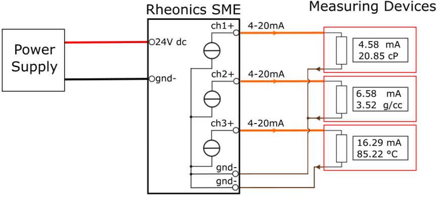
Figure 3: SME Analog Channels Example Diagram.
Notice how two Measuring Devices are connected externally, but internally all three shared the same “gnd-”. It is always important to understand the wiring diagram of the Measuring Device (especially of PLCs reading Modules) to assure a good reading.
2. Siemens AI Module 6ES7134-6GD01-0BA1This is an Analog Input Module for the ET 200SP from Siemens. It has 4 input channels that can be configured for 2- and 4-wire transmitters.
The AI Module's Diagram is presented below. It shows examples for a 2- and 4-wire connection labeled as 1 and 2, respectively.

Figure 4: AI Module 6ES7134-6GD01-0BA1 Internal Diagram [1].
3. SME Wiring Connection to Siemens 6ES7134-6GD01-0BAI ModuleA possible connection between this Siemens AI Module and SME is represented in the wiring diagram below.

Figure 5: SME and AI Module Wiring Diagram.
In this example, CH1 is connected to I1 from the AI Module, CH2 is connected to I2 and CH3 to I0. Notice how the reference pin for the measurement in I2- can be bridged with the one from I0-, since both signals in I2+ and I0+ are coming from the same transmitter (SME).
Follow Rheonics Sensor Integration with TIA portal and Diagnostics and Parameter Readings with Profinet Articles on how to read Parameters through TIA Portal.
Note: When using 4-20mA Channels take in consideration factors that can affect the readings: What can go wrong with 4-20mA Loops?
References: