Which Products are Involved?For SME-DRM (DIN rail mount) transmitter. Visit our product page to learn more about the full features.
Visit Rheonics product page: https://rheonics.com/products/
1. Preparation before scalingIf the sensor is to be installed in a tank, the sensor must be fully in the fluid. We must ensure that the sensing element is fully wetted and that the sensing area is unobstructed. Then, the sensor will measure the viscosity and/or density of the wetted area of the sensing element.

Figure 1. Sensor installed in a water tank
2. When one-point calibration is necessary to get accurate measurements in applications where the SRD is installed in a tank with water, the RCP software is required.3. Verify that baseline is correct for the sensor with the RCP software, in our scenario an SRD is used so Viscosity and density output are zero. 
Figure 2. Baseline verification
4. Go to the “Scaling” tab (This requires enabling expert mode), there open the “Select Measurement” and select the desired measure to scale. We are using a custom density model, select “Calc. Density” 
Figure 3. Selecting the custom density value.
5. When a parameter is selected, the software is going to automatically populate the unscaled value and the scaled value

Figure 4. Unscaled and scaled values from the RCP
6. Adding liquid(Water) to the tank. The readings will be affected by this change in test conditions. 
Figure 5. SRD starts readings the fluid density. Density unit kg/m3
7. Select the scaling method, “Single Point” is to be used for offset calibration (should be used when either the measurements range is kept around a narrow value, or when the sensor response and the ideal response maintain the same behavior within the sensor operation range).8. After selecting the “Single Point Scaling”, click on the read button, this will populate the “Sensor Read Out” box with the raw value currently being measured by the sensor. 
Figure 6. Click-in Sensor Read Out and populate
9. Save the read parameter (Sample 1) by click-in the button "set" 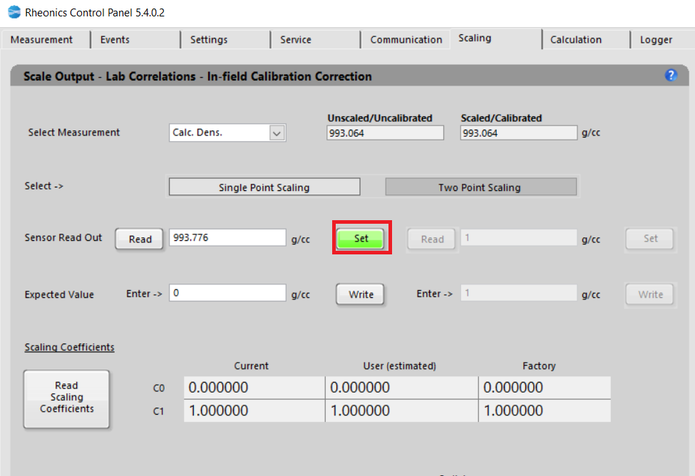
Figure 7. Saving Sample 1 by click-in set button
10. Write the “expected value” for the measurement, for the offset calibration this means that the sensor output is higher or lower than the expected reference value. Click “Write” to store the value in SMET. 
Figure 8. Saving lab value 1 of the expected value.
11. Click “SCALE” to use the stored samples to scale the SMET output. In this example notice that the software automatically shows the value that fixes the parameter to the closest value to the desired value.

Figure 9. SCALE BUTTON to load the stored samples, we noticed the closest value to fix the expected value.
10. Read the scaling coefficients 
Figure 10. Scaled coefficients.
11. New scaled values can be observed in the scaled/unscaled boxes.
Figure 12. New density value scaled.