TABLE OF CONTENTS
- Introduction to Rheonics
- Hygienic Design in Industry
- Rheonics SRV and SRD hygienic-designed sensors
- Conclusions
Introduction to Rheonics
Rheonics GmbH is a global supplier of automation instruments and solutions based on award winning process viscometers and density meters. Rheonics inline sensors fill the need in the industry for a robust, truly plug-and-play instrument for viscosity and density monitoring, with great flexibility in installation in addition to high repeatability and reproducibility of the readings.

Figure 1: Rheonics sensors
Rheonics products are widely used in many industrial applications. Rheonics online process instruments are revolutionizing process monitoring and control through a combination of key factors like high stability, reliability, robustness, and ease of use.
Rheonics sensors' main characteristics are:
- Compact form factor for simple installation
- Real-time, stable, repeatable, and reproducible measurements in Newtonian & non-Newtonian fluids
- Track viscosity and density changes over a wide range with the correct sensor configuration
- Insensitive to mounting conditions and ambient noise
- Built-in fluid temperature measurement
- Operational to high pressure and high temperature (up to and beyond 7500 psi (500 bar) and 575°F (300°C))
- Easy to clean, zero maintenance, and no re-calibration needed.
Visit EHEDG certified Rheonics process viscometer and density meter blog post
Visit 3-A certified Rheonics process viscometer and density meter blog post
Hygienic Design in Industry
A hygienic design can be defined as a set of principles in the industry to avoid cross-contamination and microbiological growth within the production lines and to favor industrial cleaning processes. Following a hygienic design leads to end-product safety and quality.
These are some of the industries in which hygienic design is of great relevance:
- Food and beverage
- Pharmaceutical
- Chemicals
As a consequence, these industries need to follow hygienic practices and procedures for cleaning, production operation, maintenance, commissioning, etc.
The cleaning procedures depend on the particular industry, environment, and application. Some common cleaning processes are Cleaning out of place (COP), which requires the dismantling of pieces from the line, and Cleaning in place (CIP), cleaning without dismantling, and using chemical fluids at specific temperature ratings and variations to clean lines. Usually, CIP is preferred over COP, due to the reduction in time and reduced exposure of personnel to chemical components.
To favor cleaning procedures, the concept of hygienic design comes into play. A hygienic design favors correct cleaning. All components that are part of a production line, such as pumps, pipes, conveyors, instrumentation, etc. are required to follow hygienic design concepts to ensure the process cleanability is within acceptable limits.
International Organizations for Hygienic Designs
International organizations help manufacturers to have guarantees that adding certified equipment or devices in line will not affect their current hygienic standards.
Some of these organizations are:
EHEDG:
The European Hygienic Engineering & Design Group is a non-profit organization founded in 1989. Its main objective is to promote food safety and quality across the food and beverage industry based on 42 guidelines that deal with specific principles in the design, construction, operation, and maintenance of equipment involved in this industry. EHEDG certification requires a theoretical review of the design and a standardized cleaning test. EHEDG’s guidelines are widely used, mainly in Europe, by food companies for food safety regulations, thus improving food safety performance.
Figure 2: EHEDG logo
3-A:
 This non-profit US-based organization was founded in 1978 and is focused on ensuring and improving hygienic designs in the dairy food, beverage, and pharmaceutical industries using very specific technical principles. Design features such as angles, radii, dimensions, surface smoothness, etc. should match 3-A standards for certification. The objective of this organization is to protect products from contamination and ensure all equipment’s surfaces in contact with the product can be mechanically cleaned and easily dismantled so it favors manual cleaning and inspection. Figure 3: 3-A logo
These two entities differ in the regulations and evaluation imposed on the design but both, EHEDG and 3-A, have the ultimate goal of improving and standardizing concepts that should be met for a hygienic design. Visit this page for a detailed view of 3-A and EHEDG organizations.
Rheonics SRV and SRD hygienic-designed sensors
Rheonics Hygienic SR-Sensors; SRV inline viscometer, and SRD inline density and viscosity meter, are used throughout different industries to monitor and control, in real-time, process fluids with extremely high repeatability and reproducibility in the readings.
EHEDG Certification (EL Class I) is available for Rheonics viscometer SRV and density and viscosity meter SRD sensors to ensure designs comply with international regulations.3-A Certification is available for Rheonics viscometer SRV, density and viscosity meter SRD sensor probes in -HS (Hygienic Series) variant and accessories. The type-SR hygienic sensors have multiple characteristics and advantages, such as:
- Accurate and reliable measurement technology
- Simple maintenance and long service intervals ensure very low downtime
- A patented technology eliminates the possibility of inaccurate measurements, for example after hot cleaning (CIP).
Hygienic designs are available in different variants and configurations. Rheonics SRV and SRD main hygienic configuration variants are shown in Table 1.

Figure 4: Rheonics Hygienic Viscometer and Density meter variants.
Table 1: Process connection codes
Sensor code | Connection type |
|---|---|
X1-12G | Threaded G1/2” - Hygienic installation available with Rheonics adapter HAW-12G-OTK2 |
X2 | Standard short probe with custom hygienic connection |
X3 | Tri-Clamp |
X4 | Flush design probe with custom hygienic connection |
X5 | Long insertion probe with custom hygienic connection. Insertion depth (A length) and connection type (B norm, size) are required. |
The differences between the sensor variants mentioned above are:
- On size: Three different probe sizes are offered: Flush (X4), Short (X1, X2, X3), Long insertion (X5) probe.
- On connection: Type-SR probes can be ordered with any connection type as long as the flange is big enough to be welded on the probe surface. For EHEDG compliance, the following connections are available:
- DIN 11853-1/2/3 min DN20
- DIN11864-1/2/3 min DN20
- DIN 11851 min DN20 in combination with ASEPTO-STAR k-flex upgrade gaskets
- ISO 2852, DIN 32676, BS 4825 Part 3 in combination with Tri-Clamp seals
- ISO 2853, BS 48525 Part 4 in combination with T-seals
- Varinline® type T and P with EPDM O-Ring in sizes B, F, N, G
SRV and SRD EHEDG certified sensors are designed in accordance with the applicable EHEDG hygienic design criteria (HDC) in document guidelines 8 (2018), 9 (1993), 10 (2007), 16 (1997), 32 (2005), 35 (2006) and with reference to specific EHEDG Supplementary Certification Requirements.
Some of the characteristics of the SRV and SRD hygienic-designed sensors are:
- Sensor surface polished finish to 0.8um Ra or better in Stainless Steel alloy EN 1.4404 or EN 1.4435/AIST 316L
- Welding done by laser with smooth and continuous welding seams.
- Design and geometry of the sensor in compliance with applicable EHEDG guidelines.
- Eliminate any surface imperfections that can create microbiological infestation.
Rheonics sensors ease for installation - guidelines
In addition to Rheonics sensors' hygienic design, installation considerations must be met to successfully ensure hygienic applications.
For EHEDG installations, the Rheonics SR sensor must be mounted according to the requirements given in EHEDG Guidelines 8, 10, and 37 [1-3]. Review Rheonics EHEDG installation guidelines on its web page here.
Some of the most noticeable requirements are the following, also applicable to hygienic installations:
- All counterparts (i.e. adapters, weldolets, pipe) involved in the installation of Rheonics hygienic sensor must be EHEDG approved.
- For installation with adapters, weldolets, and flowcells, mount the piece in a self-drained position or angle.
- In tee pieces or standpipes: the ratio between upstand (L) and the diameters difference (D − d) shall be in the relation of (D − d)/L ≥ 1 . See the figure below for reference. Rheonics flush, short, and long insertion probes have a fixed value for “d” as shown in Table 2.
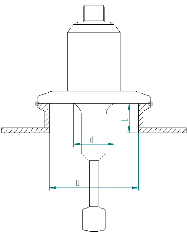
Figure 5: EHEDG requirement for standpipes
Table 2: Rheonics sensor variants
Sensor variant | "d" Dimension | Drawing |
|---|---|---|
Flush (-X4) | 14 mm |  |
Short (-X2, -X3) | 23 mm |  |
Long (-X5) | 42 mm |  |
- For the SRD, density and viscosity meter: Place the SRD end probe tip aligned with the fluid flow’s lines to create a parallel flow (see Figure 6). Consider that this is relevant when the angle α, formed by the fluid’s flow lines and sensor tip axis, is 90° or less. When α is 0° the installation creates an axial flow, in which case the end tip orientation is not relevant anymore. Perpendicular flow must be avoided because it hinders the cleaning process, as shown in Figure 6. Once installed, the probe’s end tip is not visible to know if it is aligned, to solve this issue, there is a black dot next to the M12 cable connector. This dot is aligned with the sensor tip and helps the user orient the probe as required.

Figure 6: EHEDG special requirement for SRD
Installation examples
Installation for X1 - Short Threaded Sensors
Rheonics -X1 connection process code stands for threaded connections. The G1/2” thread (BSPP norm) is offered as X1-12G code and can be used for hygienic applications thanks to Rheonics adapters.
A hygienic installation with G1/2” threads on the SRV and SRD sensors can be achieved using Rheonics HAW-12G-OTK2. This is a G1/2" hygienic weldolet suitable for pipes or tanks that requires the use of an O-Ring Ø15.1×1.6mm for sealing.

Figure 7: Rheonics HAW-12G-OTK2
Table 4: Rheonics Hygienic Flush Installation
SRV-X1-12G Flush Hygienic Installation Example | ||||
Description | Supplier | Order code | Drawing | CAD Model |
Inline viscometer - SRV | Rheonics | |||
Hygienic weldolet G1/2” for Thick walls and O-Ring seal | Rheonics | |||

Figure 8: SRV-X1-12G Flush Hygienic Installation
For walls with bigger thicknesses (>17mm), a conical or straight cut would be needed in the wall so the HAW accessory can be used or a precise machined threaded hole is done - review this drawing for more information or ask Rheonics Support Team.
Hygienic Flow Cell for SRV-X1-12G Viscometer
Rheonics offers a hygienic flow cell, HPT-12G, for the SRV viscometer with a G 1/2” connection. This HPHT flow cell requires the use of an O-ring (Ø15.1 x 1.6 mm) inside for a correct sealing connection. The inlet and outlet ports are G1/2” male ports.
Table 5: Rheonics Hygienic Flow Cell Installation
SRV-X1-12G Flow cell Hygienic Installation | ||||
Description | Supplier | Order code | Drawing | CAD Model |
Inline viscometer - SRV | Rheonics | |||
Hygienic Flow Cell | Rheonics | |||

Figure 9: SRV-X1-12G Flow cell Hygienic Installation
 Figure 10: HPT-12G Flow cell drawing
Installation for X2 - Short Sensors
The process connection code -X2 stands for any hygienic connection requested by the user that is not covered by other connection codes. For example, a hygienic connection such as DIN11851 can be used on the SRV and SRD sensors, which would also be EHEDG certified.
An EHEDG-certified installation would need the user to closely follow the (D − d)/L ≥ 1 equation, where "d" is 23mm for short sensors as described in the Ease for installation - guidelines section.
Table 6: Rheonics Hygienic short sensor in line
SRV - X2 DIN11851 DN50 Hygienic Installation Example | ||
Description | Supplier | Order code |
Inline viscometer - SRV | Rheonics | |
Tee | Rheonics | |

Figure 11: SRV DIN11851 DN50 installation in pipe

Figure 12: SRV DIN11851 DN50 in pipe drawing
Installation for X3 - Short TC Sensors
The viscometer SRV and density and viscosity meter SRD with X3 order code will have a Tri-Clamp (TC) process connection. For short sensors, the minimum TC size that can be used on the sensor is 1 1/2” (ASME BPE), which has a TC diameter of 50.5. In addition, care should be taken to select the correct matching ferrule, which should have an ID of, approximately, at least 30mm.
The SRV or SRD -X3 sensors can be installed in pipes or tanks. Next example shows the SRV-X3-15T (1.5" Tri-Clamp) mounted on a flush TC flange that can be supplied externally or from Rheonics.
Table 7: Rheonics Hygienic short sensor in tank
SRV-X3-15T Tri-Clamp Hygienic Installation Example | ||
Description | Supplier | Order code |
Inline viscometer - SRV | Rheonics | |
Flush Tri-Clamp flange | BBS-07-ZT.Z40.64- A.025.35.0 N.NAC-S38/38 | |

Figure 13: SRV-X3-15T Tri-Clamp Hygienic Installation
Installation for X4- Flush Sensors
The X4 order code stands for a flush design of the sensor with a customized process connection. For example, the SRV and SRD-X4 flush sensors can be ordered with a Tri-Clamp connection.
The main advantage of a flush sensor is its reduced exposition to the fluid, which means that it is easier to clean and disinfect with standard procedures (e.g. Clean in Place - CIP). This design is also useful for small pipes and process connections smaller (e.g. Tri-Clamp DN 20 ISO1127) than those available with the -X3 sensors.
The next example shows a flush installation using the SRV-X4 mounted on a standard off-the-shelf welded flush flange, which can also be provided by Rheonics, as in the figure below. This is a common solution for wall or bottom tank installations in some applications like Cheese Coagulation using Rheonics CoaguTrack.
Table 8: Rheonics Hygienic flush sensor in tank
SRV-X4-TC Flush Tri-Clamp Hygienic Installation Example | ||||
Description | Supplier | Order code | Drawing | CAD Model |
Inline viscometer - SRV | Rheonics | |||
Flush Tri-Clamp flange | N.NAC-S38/38 | |||

Figure 14: SRV-X4-TC Flush Tri-Clamp Hygienic Installation
VARINLINE is a trademark of GEA for a line of process connectors and housings for hygienic installation. Rheonics inline viscometer and density meter are available with Varinline process connections. In the next example, an SRV flush sensor is installed in a Varinline DN40 Housing. The matching plug at the base of the housing requires a modified plug (Rheonics order code: PLG-VNM).
Along the same lines, bigger Varinline housings can be used and standard plugs can be used.
Table 9: Rheonics hygienic sensor installation in Varinline Housing
| SRV-X4 Varinline Hygienic Installation Example | |||
Description | Supplier | Order code | Drawing |
Inline viscometer - SRV | Rheonics | SRV-X4-VNM | |
Varinline Housing DN40 | TDN40 | ||
Machined N plug | Rheonics | PLG-VNM | |

Figure 15: Rheonics hygienic sensor installation in Varinline Housing
Installation for X5 - Long Insertion Probe
The long insertion sensors (FPC) version of the viscometer SRV and density meter and viscometer SRD, allows for a customizable length and process connection. This solution gives full flexibility in mounting.
Insertion length is a configurable parameter that is specified as "A", a minimum of 56mm for the SRV and 100mm for the SRD.
The user can also select any flange or process adapter, as long as the process connection requested is 316L and is big enough to be welded in the 42mm “d” diameter of the -X5 sensor (See table 2).
The next installation example is a wall tank installation. For a hygienic and EHEDG installation, the (D − d)/L ≥ 1 equation, described in the Table 2, should be followed where d is 42mm for X5 variants.
Table 10: Rheonics hygienic long insertion sensor installation in tank
SRD-X5 Hygienic Installation Example in Tank | ||
Description | Supplier | Order code |
Inline hygienic viscometer - SRD | Rheonics | |

Figure 16: SRD-X5 Hygienic Installation Example in Tank.
Conclusions
Rheonics offers inline viscometers and density meters with a hygienic design through its Type-SR sensors SRV and SRD. These are also built according to EHEDG guidelines to ensure strict conformance to standards.
Installation is key to avoid dead zones or stagnation zones that can affect the cleanability and the readings of the hygienic sensors.
Feel free to contact Rheonics at info@rheonics.com for sales and application related questions and support@rheonics.com for information on potential installation setups.