What products are involved?
Rheonics SRV viscometer, SRD density-viscosity meter, DVP gas density-viscosity meter and DVM HPHT density-viscosity meter
What is the purpose of this article?
This article describes the procedure for integrating Rheonics Smart Module Electronics unit (SME) 4-20mA signal into the Micrologix PLC Family using RSLogix.
1. Overview
Rheonics viscosity and density meters bring fluid intelligence and process control to a broad range of customer applications. Each sensor is equipped with a Smart Module Electronics unit (SME), which drives the sensor, evaluates its response, and enables communication through all major communication protocols
In the world of industrial automation, Allen-Bradley PLCs remain reliable and well-established. As a result of their proven track record and extensive support infrastructure, these PLCs remain a critical component of many systems. This article guides integrating an SME's analog 4-20 mA signal with a MicroLogix PLC
 Figure 1. MicroLogix 1100 PLC. Image sourced from Rockwell Automation's website.
2. SME’s 4-20 mA channel wiring
The Rheonics Smart Module Electronics (SME) includes three in-built output channels for 4-20mA signals, labeled CH1+, CH2+, and CH3+ on the SME’s housing. In this setup, CH1+ is connected to get the viscosity output.

Figure 2. SME-DRM 4.20 mA outputs
For more information on the SME’s 4 -20 mA channels, take a look at Connecting 4-20 mA outputs. It’s crucial to make sure the sensor cables are wired properly as well: Connecting sensor cable colored wires to transmitter electronics
3. 4-20 mA on a Micrologix PLC
Micrologix base units do not have embedded 4-20mA analog inputs. There are two approaches to address this issue:
- Using a 500 Ω resistor.
- Using an expansion I/O module.
A 500Ω resistor, according to Ohm's Law, would convert the SME current output into a measurable voltage that a MicroLogix base unit can read. However, this approach comes with trade-offs, which will be discussed later in the article. It's always recommended to use a solution supported by the manufacturer whenever possible.
4. 4-20 mA on Base Micrologix PLC: Using a 500Ω Resistor
A 500 Ω resistor can create a voltage drop across the Micrologix input terminals. This method can be an effective low-cost solution for applications that don't require high accuracy. However, high-precision resistors are recommended to avoid inaccurate readings.
Occasionally, embedded analog inputs have lower resolutions than dedicated I/O modules. Table 1 provides important information about a MicroLogix 1400 embedded analog input, particularly its resolution. Depending on the customer’s application and requirements, a 12-bit resolution may or may not be sufficient, for cases where a higher resolution is needed, the 1762-IF4 module, which offers 15-bit resolution (Table 2), might be more appropriate.
| Description | T766-L32AWA/A, T766-L32BWA/A, T766-L32BXB/A |
| Voltage input range | +0...10V DC - 1 LSB |
| Type of data | 12-bit unsigned integer |
| Input coding | 0...4095 |
| Voltage input impedance | >199 KΩ |
| Input resolution | 12 bits |
Non-linearity | ±0.05% of full scale |
| Overall accuracy | ±0.1% of full scale |
| Update time | 100/20/16/67 ms (selectable) |
| Voltage input overvoltage protection | 10.5V DC |
| Field wiring to logic isolation | Non-isolated with internal logic |
Table 1. Analog Input on Micrologix 1400
4.1 Micrologix 0-10 V input wiring
For this example, a Micrologix 1400 will be used. Wire a 500Ω resistor as shown on Figure 3. The high parallel resistance on the analog inputs (199 KΩ according to Table 1) will result in a small loss of precision, though the impact is minimal.
 Figure 3. Micrologix Wiring
Finally, wire the two cables that will carry the 4-20 mA signal from the SME to the Micrologix’s analog input. The current will pass through the resistor and provide a 0 -10 V signal. Note that while the resistor is specified as 500Ω, the actual value is 492Ω. Using a high-precision resistor will minimize this difference.
5. 4-20 mA on Micrologix PLC: Using an Expansion Module
Wiring the SME’s channels to an expansion module such as a 1762-IF4 is the recommended approach. This alternative is the ideal solution to a more robust and accurate system and reliable process control.
Table 2 is extracted from Rockwell’s documentation. It shows data ranges for 0 -10 V and 4 - 20 mA analog inputs for 1762-IF4 expansion modules.
| Normal Operating Range | Full Scale Range | Raw/Proportional Data | Scaled for PID |
0 to 10 Vdc | 10.5V dc | 32760 | 16380 |
| 0.0V dc | 0 | 0 | |
4 to 20 mA | 21.0 mA | 32760 | 16380 |
| 20.0 mA | 31200 | 15600 | |
| 4.0 mA | 6240 | 3120 | |
| 0.0 mA | 0 | 0 |
Table 2. Analog Input on 1762-IF4 Expansion Module
A quick comparison between Table 1 and Table 2 reveals that the analog inputs on the 1762-IF4 module offer a major advantage: improved resolution, along with dedicated inputs for 4-20 mA signals, thus avoiding the need to add a resistor or risk losing precision. The data from both tables will be used as a reference for programming in RSLogix, particularly for scaling purposes.
5.1 1762-IF4 4-20 input wiring
Wiring an IO expansion module is straightforward. Connect two wires between the SME’s analog 4-20mA output to one of the expansion module terminals. The expansion modules expect two connections: IN0+ and IN0- were used in Figure 4 example.
 Figure 4. 1762-IF4 Expansion Module input wiring
6. SME’s channel configuration on RCP
The 4-20mA Settings in the “Service” Tab allows the user to read and set the upper and lower limits for each of the channels, as well as to set which parameter is assigned to each of them. In Figure 5, viscosity is set on Channel 1 with an Upper Range Value (URV) of 3,000 cP, density on Channel 2, and temperature on Channel 3.
 Figure 5. 4-20mA settings box
For more information on how to set up an analog signal on the RCP, take a look at:Analog signals setup with the RCP
7. Input configuration on RSLogix500
7.1 Input Configuration
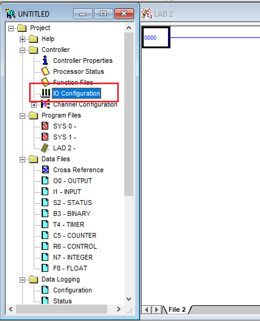
Regardless of whether a 0-10V or a 4-20 mA signal is used, the value will be stored in the Input Data File. To access the file, look for the Input icon on the left bar, as shown in Figure 6.
 Figure 6. Input Data File
The user is reminded that the resolution and the actual integer value stored on the file will depend on the input used (see Tables 1 and 2). For example, if using the embedded input I:0.4 (0-10 V), after connecting the sensor to the PLC, a value between 0 and 4095 (12-bit resolution, as shown in Table 1) is expected to be stored at I:0.4.
 Figure 7. Inputs on RSLogix
If an Analog Input from expansion module 1762-IF4 is used, additional configuration is needed. Click on IO configuration, on the left bar.
Select the appropriate card and double-click it to add it, in this case 1762-IF4 is selected (Figure 9). The new card will appear on the left side. This stack will show all the selected cards for the program. After clicking the newly added 1262-IF4 card, a configuration window will appear.,
For a 1762-IF4 analog input, the most basic configuration fields needed are Input Range and Data Format. Both found in the tab Analog Input Configuration (Figure 9)
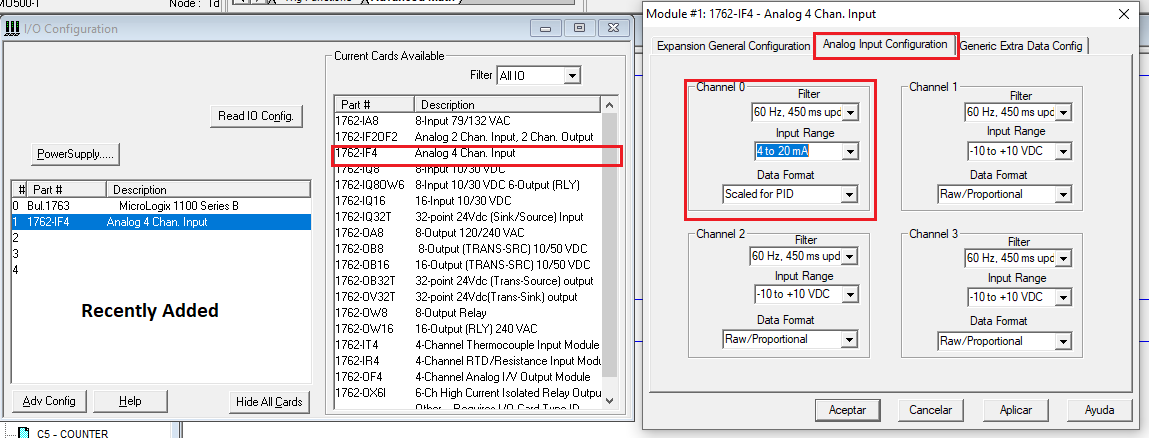
The Input Range describes the type of signal to be used: either -10 to 10 VDC or 4-20 mA. In this case, the 4-20 mA signal is selected. The Data Format determines how the PLC will process the raw data, and the selected option will affect how the analog value is stored in the Input Data File (Figure 7). The available options for the 1762-IF4 are displayed in Figure 10.

Figure 10. Data Format options
For completeness sake, Table 3 lists all the available options in RSLogix.
Raw/Proportional Data | The value at the controller is proportional to the selected input and scaled into the maximum data range allowed by the bit resolution of the A/D converter (for example, 16-bit resolution provides a -32,767 to +32767 full range for a +/- 10vdc user input. Refer to the instruction manual for your input card for a table of valid formats and data ranges. |
Engineering Units | The module scales the analog data to the actual current or voltage values for the selected input range. The resolution of the engineering units is dependent on the converter resolution. Refer to the instruction manual for your input card for a table of valid formats and data ranges. (This option only applies to the 1769-IF4 module). |
Scaled for PID | The value at the controller is an integer with 0 representing the lower range and 16,383 representing the upper range. The MicroLogix uses this range in its PID equation. The amount over and under range is also included. Refer to the instruction manual for your input card for a table of valid formats and data ranges. |
Percent Value | The input data is presented as a percent of the full range (for example, -0.5V to 10.5V = -5% to 105%.) Refer to the instruction manual for your input card for a table of valid formats and data ranges. (This option only applies to the 1769-IF4 module). |
Table 3. Data Format Options - RSLogix
Ultimately the option selected will dictate the values on the Input Data File that will be used to “scale” the analog signal to a useful unit, like pressure, cP or ºC.
Raw/Proportional Data option will use the entire resolution to display the signal, which means the 4-20 mA will be converted to an integer up to 32,760 (Table 2).
Scaled for PID will scale it to the full scale that RSLogix, as a convention, uses in the PID blocks; converting the electric value to an integer up to 16380 (Table 2). Selecting Scaled for PID takes the user one step closer to using the same “language” for all its blocks. It's a matter of convention and personal preferences.
For most programmers, working with Engineering Units would be the best option since the signal will be scaled automatically to the selected Input Range while using most of the resolution, therefore getting a useful unit without further scaling; however, there is no such option for 1762-IF4.
For this case, Scaled for PID is selected; however, selecting one over the other will make no difference since the signal will still need further processing to get a useful value, for this case a viscosity value in cP.
7.2 SCP Block
No further configuration is needed for the IO. The MicroLogix will be able to read the 4-20 mA sensor and store the value in the Input Data file. To implement control logic, the integer value needs to be scaled to the appropriate viscosity unit using an SCP block.
The SCP block takes an input value and scales it to a range determined by creating a linear relationship between input min and max values (what integer values we get from the sensor) and scaled min and max values (what values in cP we want and are configured on the RCP), as shown in Figure 12. The scaled result is returned to the address indicated by the output parameter in viscosity units.
First, Look for SCP block under Advanced Math (Figure 11)
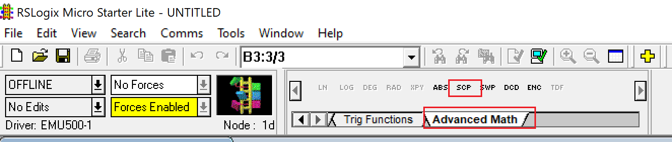
Click the SCP option to add the block to a rung.
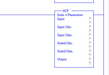
Input: Analog input stored on the Input data file. It's the viscosity value scaled to an integer, depending on the Input Range and Data Format configuration selected on the IO configuration step (Figure 9)
Input Min and Input Max: Minimum and Maximum values expected from the Input.
Scaled Min and Scaled Max: Range configured for the sensor on RCP (Figure 5)
Output: Scaled value in the same units as Scaled Min and Max.
7.3 Signal Scaling for 4- 20 mA signal
Let’s take a look at a first example: 4-20 mA, Scaled for PID. Scaled for PID means that the PLC will transform the 4-20 mA to a number between 0 and 16380; the minimum and maximum expected values for the sensor showed on Table 2, can be used here: 3120 for 4mA and 15600. If a different expansion module is used, refer to the manufacturer's manual for the actual range.
If no documentation is available or the programmer is unsure about the working range of the expansion module analog inputs, a practical approach is to connect the sensor to the PLC and observe the actual values stored in the Input Data file (e.g., I:1.0) for both the 4 mA and 20 mA signals. These values can then be used as the Input Min and Input Max.
Lastly, scaled min and scaled max is the viscosity range configured for the sensor: 0 - 3,000 cP.
7.4 Signal Scaling for 0-10 V signal
For the embedded 0-10V signal, there are no Raw/Proportional or Scaled PID data settings like those configured for the analog input on the Expansion Module. Table 1 shows the embedded input description: an input value in a range between 0 and 4095 is expected with no additional info provided, which means that the 0-10V signal will be scaled to an integer between 0 and 4095 and stored in the Input File; however, the actual minimum and maximum values are still needed for the SCP configuration. These most likely would be 0 and 4095 or really close.
If the user wants to be thorough, they can follow the approach described in Section 7.3: “Connect the sensor and observe the values in the Input Data file…” in this case, for both 0V and 10V signals. Once the minimum and maximum values are known, these can be used to configure the SCP block.

7.5 Signal Scaling Output
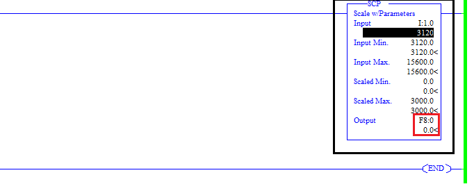
Figures 15 and 16 show the scaling by the SCP blocks for a 4-20 mA signal, using the SCP block configured for a 1762-IF4 card (Figure 13).
Since Scaled for PID was selected in the I/O settings, the value in I:1.0 is scaled to the PID range by the PLC. The SCP block then takes this PID-scaled integer and, using the Input Min, Input Max, Scaled Min, and Scaled Max, creates a linear relationship to convert the signal into a useful unit such as cP (centipoise). The final scaled value is stored as a float in F8:0.
For Figure 15, an analog integer of 3120 is stored on I1.0, which represents the Input Min configured. This value is actually what the block gets when a 4 mA signal input is read; the calculated value on F8:0 is 0 cP as expected.
In the same way, for an analog integer value of 10,500 stored in I1.0 (Figure 16), a corresponding calculated value of 1,774.038 cP is stored in F8:0.

The newly calculated viscosity value from the SCP block can then be used for further control applications, such as setting high or low limits, defining a setpoint, or displaying the value to an operator, among other uses.
8. Analog vs. Digital - Pros and Cons
Analog communication, particularly 4-20 mA current signals, has been a longstanding standard in industrial settings. An analog signal's primary advantage is its simplicity. This simplicity means it requires very little configuration, and analog components are generally less expensive, which makes for great option for basic measurements.
However, analog communication comes with limitations:
Only one piece of information can be transmitted per channel, which makes it unsuitable for transferring diagnostic data or multiple measurements at the same time.
Analog signals are also more prone to electrical interference, which can degrade signal quality in electrically noisy industrial environments.
Over time, analog systems may need calibration to maintain accuracy, adding to maintenance efforts and potential downtime.
Many limitations of analog systems can be addressed by using digital communication protocols such as Modbus, Profinet or Ethernet/IP, all of which are supported by Rheonics sensors
Digital signals allow multiple data type transmission over a single communication interface at once. This way, measurements, device status, diagnostic information, and even control commands can be exchanged between devices and control systems.
They are inherently less susceptible to electrical noise, which makes them ideal for industrial settings with high electromagnetic interference. This is crucial for maintaining accurate and consistent data transmission and a reliable process control.
Digital networks are scalable and flexible, allowing multiple devices to communicate over a single network cable or wireless connection
The choice between analog and digital communication ultimately depends on the application, however, for a reliable viscosity control, it is heavily recommended the use of digital communication. For detailed information on all available communication options for Rheonics viscosity and density meters, visit
9. References
Rockwell Automation Publication 1766-IN001F-EN-P.
Rockwell Automation Publication 1762-RM001H-EN-P.
Micrologix Instruction Set Help.