
| What is the purpose of this article? This guide explains how to read data from a Rheonics Sensor Module Electronics (SME) via Modbus TCP with Node-RED and publish it to an MQTT broker (HiveMQ in this example). The main goal is to enable remote visualization of sensor data from any location. This is achieved by using cloud-based MQTT brokers for accessible data exchange, combined with Node-RED, a flexible and user-friendly tool to read, process, and publish sensor data into an MQTT broker. |
TABLE OF CONTENTS
1. Prerequisites
1. Rheonics SME with Modbus TCP enabled
- SME connects to the sensor probe and transmits the data using different industrial communication protocols. Modbus TCP protocol is used in this article.
2. Node-RED (Windows 10/11 or Linux)
- A visual programming tool used to collect, process, and route data. In this case, it acts as an intermediary that allows sending sensor data to an MQTT broker.
- node-red-contrib-modbus: a Node-RED add-on that enables communication with Modbus devices.
3. MQTT broker (HiveMQ in this article)
- A cloud-based MQTT message broker acts as an intermediary between clients that send (publish) and receive (subscribe) data. In this case, it transmits the sensor data received from Node-RED to Ignition for remote visualization.
Following this architecture, data from Rheonics sensors can be sent to an MQTT broker to visualize readings in any MQTT-compatible platform such as Ignition SCADA.
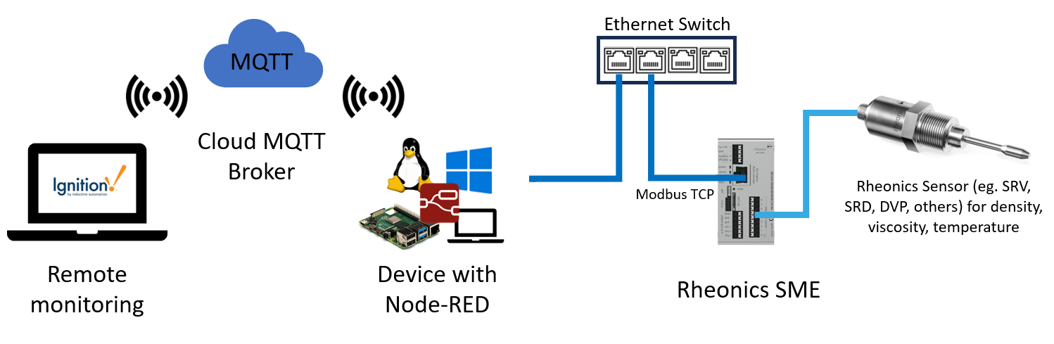
Figure 1. Architecture of Rheonics, Node-RED, MQTT, and Ignition integration.
2. Obtaining Data in Node-RED
The goal is to obtain sensor data via Modbus TCP in Node-RED and send it to an MQTT broker. The completed Node-RED flow is shown below, and the following steps explain how to build it.
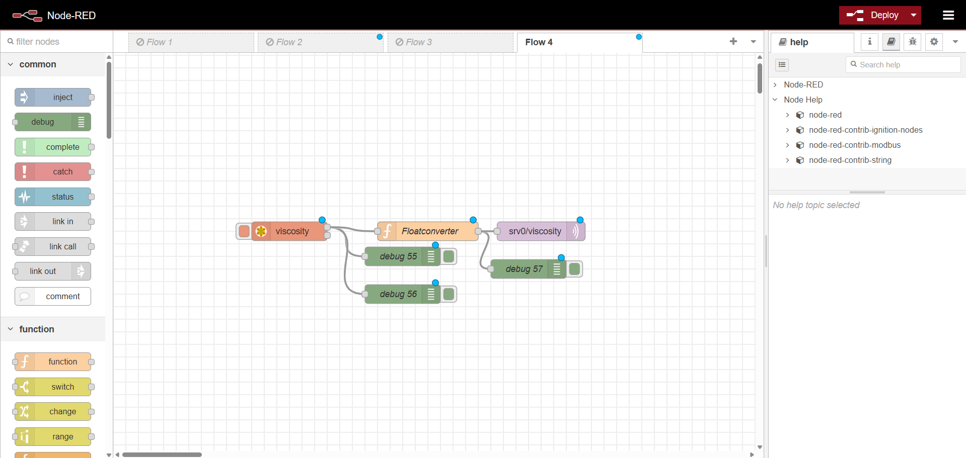
Figure 2. Node-RED flow for sending data from Modbus to an MQTT broker.
| To learn the basic steps for setting up Node-RED and using the modules mentioned in this article, visit Node-RED Setup and MQTT for Rheonics Sensors. |
2.1. Open Node-RED
1. After installing Node-RED correctly, in a terminal, paste the following command to start running Node-RED:
| node-red |
2. The terminal displays the corresponding version and indicates that Node-RED is running correctly. The server URL appears after Server now running at — in this case, http://127.0.0.1:1880/.
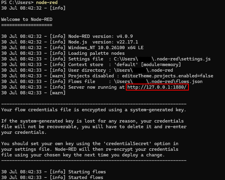
Figure 3. Node-RED running in a terminal.
3. Paste the link in a browser to load the Node-RED editor.
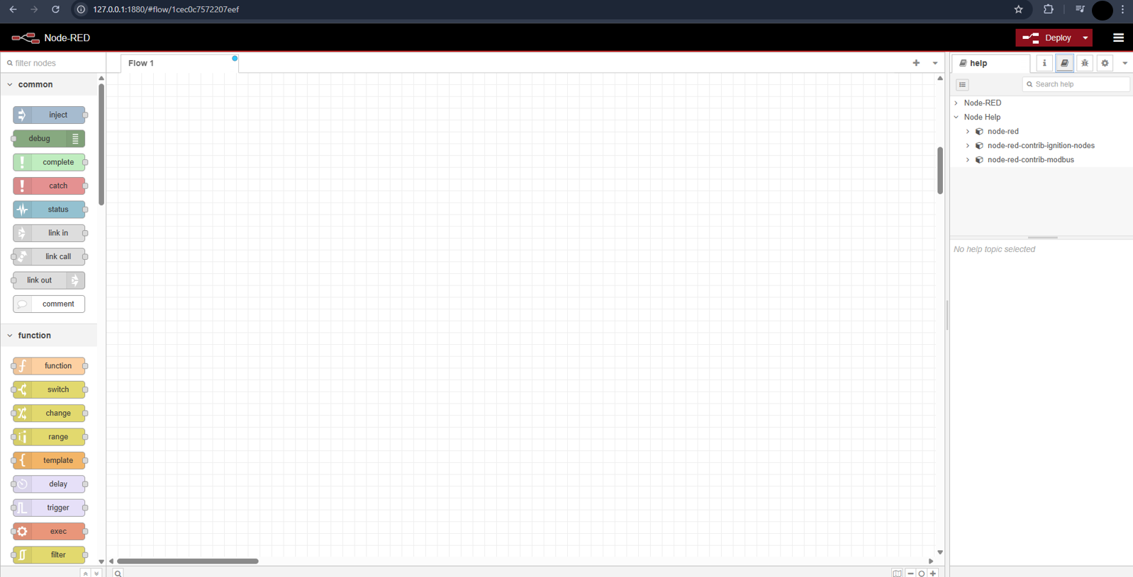
Figure 4. Node-RED editor.
2.2. Add a Modbus-Read Node
To obtain the sensor data through Modbus TCP, use the node-red-contrib-modbus module.
1. Drag a Modbus-read node onto the flow.
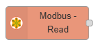
Figure 5. Modbus-Read node.
2. Double-click to configure:
- Name: Viscosity (this is just the label of the node)
- Function Code: FC4 – Read Input Registers
- Address: 40 (viscosity register). The rest of the input parameters can be found in Modbus TCP – Input Registers.
- Quantity: 2 (float = 2 registers)
- Poll Rate: 3s (depends on frequency of data reading desired)
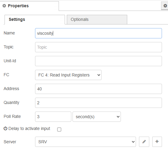
Figure 6. Modbus-Read Node Configuration.
3. Click on the Server field and press the plus icon to add a new Modbus TCP client. In this case, it corresponds to the SME:
- Type: TCP
- Host: IP address of the SME
- Port: 502 (default)
- Unit ID: 255
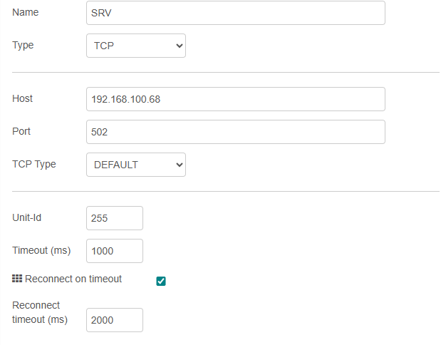
Figure 7. Modbus Client Configuration.
2.3. Add a Function Node to Decode Float
The Modbus-Read node returns the values of the registers, which need to be transformed to obtain the value of viscosity. Add a function node to convert the two 16-bit registers into a float value.

Figure 8. Function node.
1. Drag a function node onto the flow.
2. Double-click on the node and add the following code to the On Message section. This returns the viscosity as a float.
| let buffer = Buffer.alloc(4); buffer.writeUInt16BE(msg.payload[0], 0); buffer.writeUInt16BE(msg.payload[1], 2); msg.payload = buffer.readFloatBE(0); return msg; |
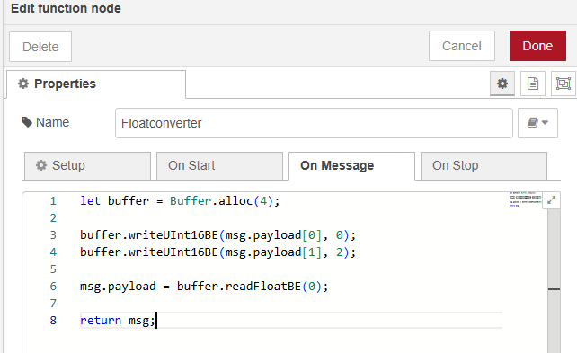
Figure 9. Function node – float conversion.
2.4. Add an MQTT-Out Node
Add an MQTT-out node to publish the sensor data to the broker — in this case, the HiveMQ broker.
| To learn how to create and configure the HiveMQ broker, refer to HiveMQ Broker Integration with Rheonics. |
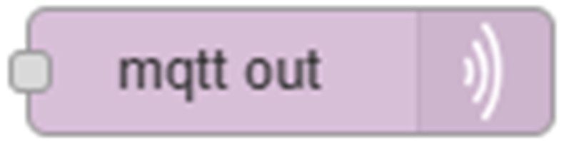
Figure 10. MQTT-out node.
1. Drag an MQTT-out node onto the flow.
2. Double-click on the node to configure its properties:
- Topic: srv/viscosity (name of the topic where the viscosity data will be published)
- QoS: 1 (this allows the message to be received at least once)
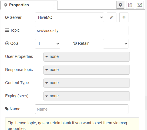
Figure 11. MQTT-Out Node Configuration.
3. Add an MQTT broker by pressing the plus icon next to Server to add the HiveMQ broker.
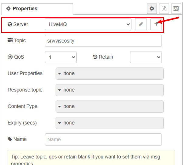
Figure 12. MQTT broker addition.
4. Next, fill in the properties of the MQTT broker as follows:
- Name: Desired name for the broker
- Server: HiveMQ connection URL
- Port: Port used by the broker
- Use TLS: Enable if using encrypted communication
- Protocol: MQTT V5
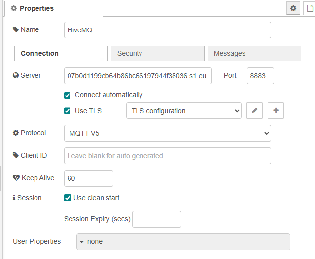
Figure 13. HiveMQ Broker Configuration – Connection tab.
5. Go to the Security tab of the HiveMQ broker configuration and fill it with the broker's credentials:
- Username: username credentials in HiveMQ broker
- Password: password credentials in HiveMQ broker
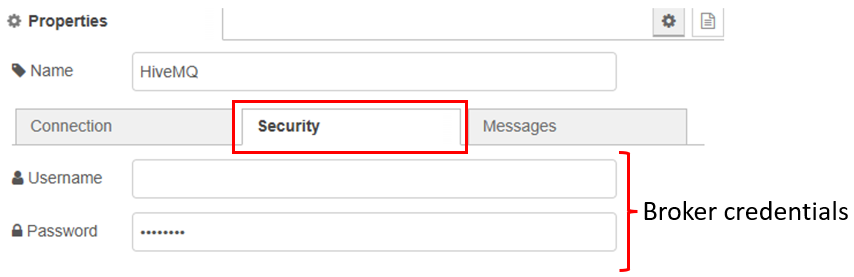
Figure 14. HiveMQ Broker Configuration – Security tab.
2.5. Deployment and Final Visualization of Node-RED Flow
1. After adding and configuring the nodes correctly, press the Deploy button to run the flow.
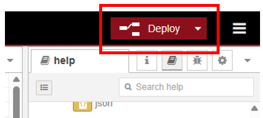
Figure 15. Deployment of Node-RED flow.
2. The final flow looks as follows:
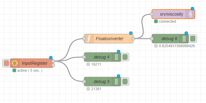
Figure 16. Complete Node-RED flow for Modbus to MQTT.
3. Repeat the same procedure to obtain other parameters of the SME by modifying the address and topic.
| To learn how to integrate Ignition SCADA with Rheonics sensors via MQTT, refer to Using Ignition SCADA to Visualize Rheonics Sensor Data via MQTT. |