What is the purpose of this article?
This article demonstrates how to integrate the USR-W610 RS232/RS485 to Wi-Fi and Ethernet Converter with Rheonics sensors to transmit data over a Wi-Fi network and access it remotely.
What products are involved?
This article is based on using the Rheonics Sensor Module Electronics (SME) and the USR-W610 RS232/RS485 to Wi-Fi and Ethernet Converter.
TABLE OF CONTENTS
- 1. Overview
- 2. Prerequisites
- 3. USR-W610 Setup through built-in Web server
- 4. Accessing Rheonics SME Data via the USR-W610
- 5. Resources
1. Overview
To enable wireless data access, Rheonics offers the USR-W610 RS232/RS485 to Wi-Fi and Ethernet Converter as an option. The USR-W610 transmits Modbus RTU data from the Sensor Module Electronics (SME) over a Wi-Fi network, enabling wireless communication and remote access. This article describes how to integrate a Rheonics sensor with the USR-W610 to transmit sensor data over Wi-Fi for remote monitoring and visualization.
The USR-W610 is provided in its default Access Point (AP) mode, which allows connecting to the module wirelessly and performing the corresponding configurations to access a Wi-Fi network. However, station (STA) mode is used to read the sensor's data and connect to a Wi-Fi network, as shown in the following diagram.

2. Prerequisites
- Rheonics SME with Modbus RTU enabled
- USR-W610 RS232/RS485 To Wi-Fi and Ethernet Converter
3. USR-W610 Setup through built-in Web server
There are three possible ways of configuring the USR-W610, as AP, STA and as AP+STA.
- Access Point (AP): In this case, the USR-W610 acts similar to a router, which means other devices can connect to it.
- STA (station): In this configuration, the USR-W610 connects to an existing access point like a router allowing the device to access internet.
- AP + STA : Combines both modes.
In this article, STA configuration is explained to receive data from Rheonics SME through its serial port.
3.1. USR-W610 Configuration
The USR-W610 is provided in Access Point (AP) mode by default, creating its own Wi-Fi network that other devices (laptops, tablets, others) can connect to. In AP mode, the corresponding configurations are made to use STA mode, so the USR-W610 connects to an existing Wi-Fi network and transmits Rheonics sensor data through it. Other devices connected to the same Wi-Fi network can visualize the sensor data as seen in the figure.

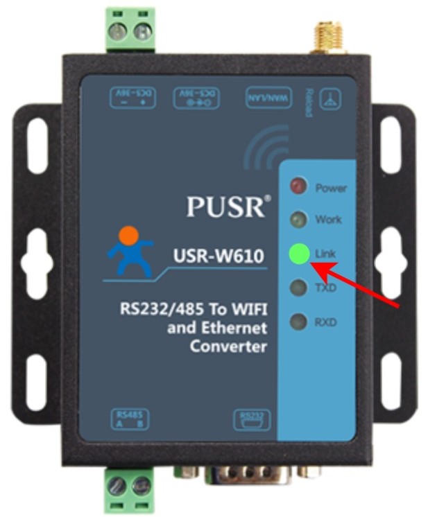
1. After powering the USR-W610, open the available Wi-Fi networks and connect to Rheonics Network.

2. The Link LED should light up after a successful network connection.
3. Access the web server by entering the default IP address in a browser and the credentials provided on the device label.
- IP: 10.10.100.254 (default)
- User: admin
- Password: admin

4. In the web server of the USR-W610, select STA Interface Setting.

5. Click on Search to look for Wi-Fi networks.

6. A window with all the available Wi-Fi networks is displayed. Select the Wi-Fi network used and click on Apply.

7. In Pass Phrase, enter the Wi-Fi password and click on Apply.

8. After each modification, click on Device Management to restart the device.

9. Once in Device Management, click on Restart so the configurations are saved correctly.

10. A rebooting message should appear. Wait for a few seconds, and then continue.

11. Next, in DHCP Mode in the STA Interface Setting select the WAN Connection Type as STATIC (fixed IP), fill out the properties, and click on Apply.
- IP address: Make sure it is in the same range as the Wi-Fi network you are connecting to. This can be checked in the network connection details. In this case, the IP 192.168.100.73 is selected because of the Wi-Fi network properties.

- Subnet Mask: 255.255.255.0
- Default Gateway: 192.168.100.1

12. Click on Mode Selection.

13. Select STA Mode and in Data Transfer Mode select Modbus TCP <--> Modbus RTU. Click on Apply.

14. After updating the USR-W610 configuration, the Link LED should light up after Wi-Fi connection has been successfully established.

15. Use the IP address configured in Step 11 to access the web server, then enter the default credentials.

3.2. Modbus RTU parameters configuration
To configure the serial port parameters of the Rheonics SME, follow the next steps.
1. Enter the USR-W610 and select Application Setting.

2. Configure Modbus RTU parameters according to Rheonics guideline in Connecting Modbus RTU (RS-485) outputs
- Baudrate: 38400
- Data Bits: 8
- Parity: Odd
- Stop: 1
- Flow control: Disable
- 485 mode: Enable
- Baudrate adaptive (RFC2117): Enable

3. Under Network A Setting, configure as follows and click on Apply.
- Mode: Server
- Protocol: TCP
- Port: 502
- Server Address is configured automatically depending on the router

4. Accessing Rheonics SME Data via the USR-W610
Once the USR-W610 configuration is complete, the Rheonics sensor data can be accessed wirelessly over Wi-Fi.
4.1. Wiring the USR-W610 to the Rheonics SME
Wire the SME to the USR-W610 serial port as shown in the diagram.

4.2. Reading Sensor Parameters Using Modbus Poll
1. To read data using Modbus Poll, open the Modbus Poll software.

2. Click on the Connection Tab and select Connect.

3. Modbus RTU communication is converted to Modbus TCP due to the configuration done in the setup. On Connection select Modbus TCP/IP.
- IP address: the static IP chosen in the STA Interface Setting during the configuration
- Port: 502 (default)

4. Sensor data is available in the input registers. The table below shows the commonly used registers.
Parameter 12 | Viscosity Last Good | |||
136 | 300137 | 2 | Float32 | Parameter 12 value as float |
Parameter 13 | Density Last Good | |||
144 | 300145 | 2 | Float32 | Parameter 13 value as float |
Parameter 2 | Temperature median | |||
56 | 300057 | 2 | Float32 | Parameter 2 value as float |
5. Click on Setup and Read/Write Definition.

6. Configure the following parameters to read Viscosity Last Good and click OK.
- Slave ID: 1 (default)
- Function: 04 Read Input Registers (3x)
- Address: 136
- Quantity: 2

Take into consideration that the SME slave ID remains the same when Modbus RTU is converted to Modbus TCP. Ensure that the slave ID matches the value configured in your SME settings. |
7. Configure any additional input registers as required. The corresponding values should now be displayed correctly.

5. Resources
- Electronics and Communications
- Modbus RTU (RS-485)
- Connecting Modbus RTU (RS-485) outputs
- Modbus TCP - Protocol
- Modbus Input Registers
- USR-W610 RS232/485 to Wi-Fi/Ethernet Converter