
What products are involved?
SRV – Inline Viscosity Meter
What is the purpose of this article?
This article describes how to integrate the Rheonics Sensor Module Electronics (SME) via Modbus RTU with the CAN serial communication protocol, which is commonly used in industrial environments with high electrical noise for monitoring and control of variables.| Short answer: This guide shows how to convert Modbus RTU data from a Rheonics SME into CAN messages using a Waveshare RS232/485/422-to-CAN converter, and how to verify the resulting communication with a Kvaser USB-to-CAN interface and CanKing software. |
TABLE OF CONTENTS
- 1. Overview
- 2. Wave Share RS232/485/422 to CAN Converter Configuration
- 3. Testing the Conversion Using a USB to CAN Interface
- 4. Rheonics SME Data Integration
- 5. References
1. Overview
The Controller Area Network (CAN) is a serial communication protocol that uses a serial bus system to share information between electronic devices. Electronic modules can communicate over a single CAN interface instead of multiple input/output signal connections, which reduces wiring costs and allows operation without a "host" computer. All devices — also called CAN nodes — can read every message on the bus, but they identify messages using a message identifier (ID) rather than a device address.
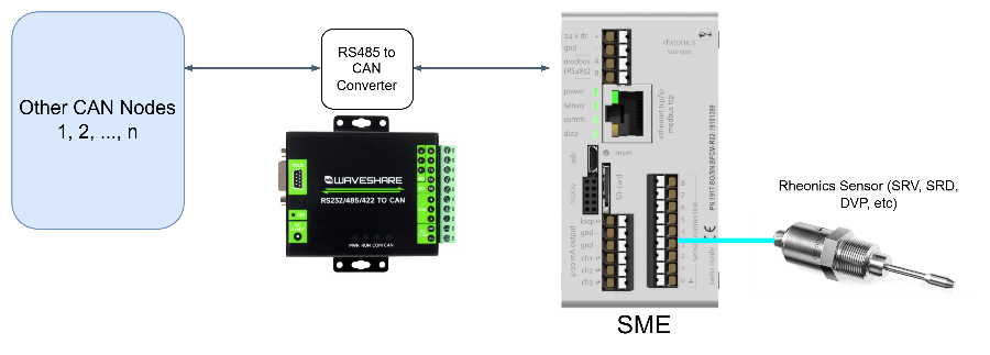
In this application, the Modbus RTU data received from the Rheonics SME must be converted into CAN messages so that other CAN nodes on an industrial plant network can share the information acquired by Rheonics sensors, such as the SRV. This article demonstrates communication between a Rheonics SME and a second CAN node (a PC), using a Modbus RTU-to-CAN converter and a Kvaser USB-to-CAN interface.
2. Wave Share RS232/485/422 to CAN Converter Configuration
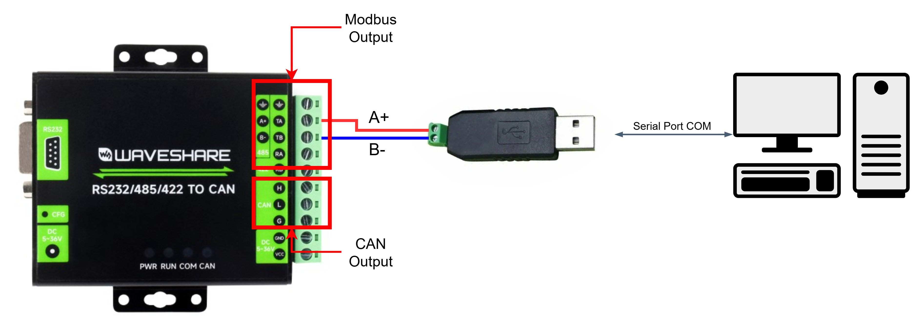
To set up the converter parameters, connect the device to the PC through a USB-to-RS485 converter attached to the RS485 port. After identifying the assigned serial port (using Device Manager), download, extract, and open the WS-CAN-TOOL [1].
2.1 Configuration in WS-CAN-TOOL
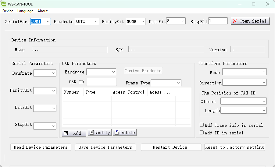
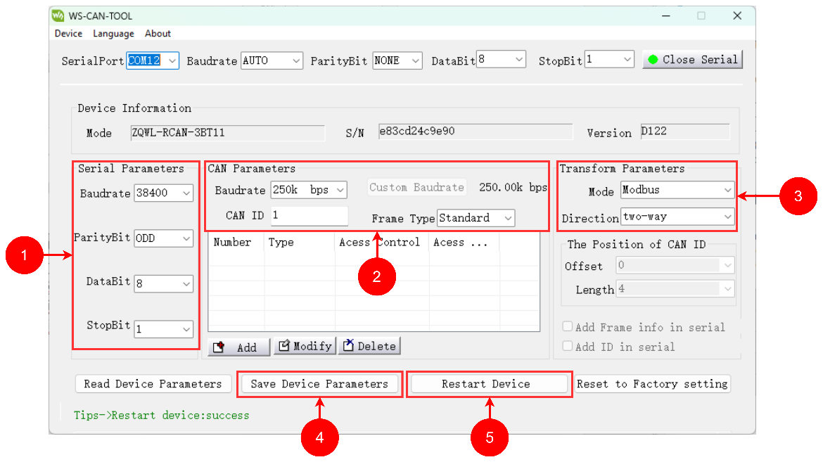
- The software sets the parameters of the RS485 and CAN ports and the conversion mode. Select the identified COM port number of the converter, keep the remaining values at their defaults, and select Open Serial.
- Once the serial port is open, all device information is shown in the software after pressing Read Device Parameters. Change the serial parameters to match the Rheonics SME Modbus RTU port.
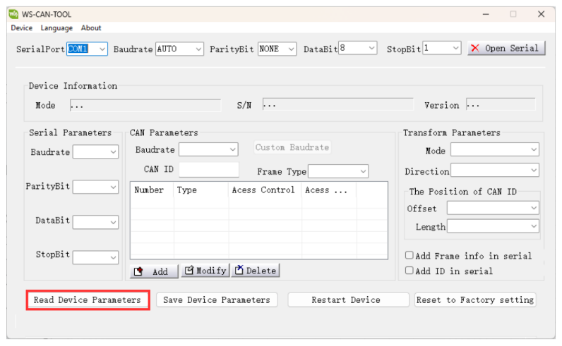
Table 1: Modbus RTU default parameters in Rheonics SME
| Parameter | Value |
|---|---|
| Baudrate | 38400 |
| ParityBit | Odd |
| Databit | 8 |
| Stopbit | 1 |
Apply the following settings:
- CAN ID: the ID of the required device.
- Frame Type: select Standard Frame (2.0A, compatible with the CANopen protocol). Extended Frame (2.0B) is also available and is compatible with the J1939 protocol.
- Transform Parameters: choose the Modbus option.
Finally, click Save Device Parameters, then Restart Device. The next time the device needs to be configured, use the current baud rate, parity bit, and other active values to open the serial port — not the factory defaults.
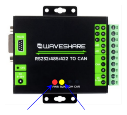
- After the restart, check which LEDs are active on the converter. If the device is working correctly, the PWR LED lights up and the RUN LED blinks.
2.2 Connection with Rheonics SME
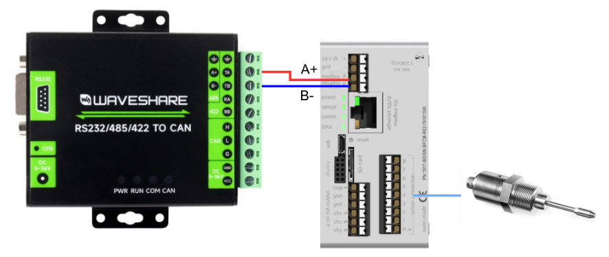
Disconnect the USB-to-RS485 converter from the device. Using the wiring diagram below as a reference, connect the SME to the converter. The Rheonics SME ships with Modbus RTU enabled and configured with the default settings listed in Table 1. These settings can be changed in the Rheonics Control Panel (RCP). At this point, the Rheonics SME and converter can be integrated into a CAN network.
| → See: Modbus Organization partnership with Rheonics and Connecting Modbus RTU (RS-485) outputs for more information on Modbus RTU configuration. |
3. Testing the Conversion Using a USB to CAN Interface
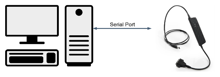
The converter has two connectors: a USB Type-A port and a DB9 connector. To configure the interface, connect the USB port to the PC — this powers on the device. To configure the CAN channel, download the Kvaser driver for the interface model and the CanKing 7.5 software from the official Kvaser site [2].
3.1 Configuration in CanKing 7.5.0 Software
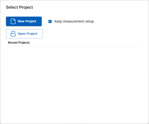
- Select New Project.
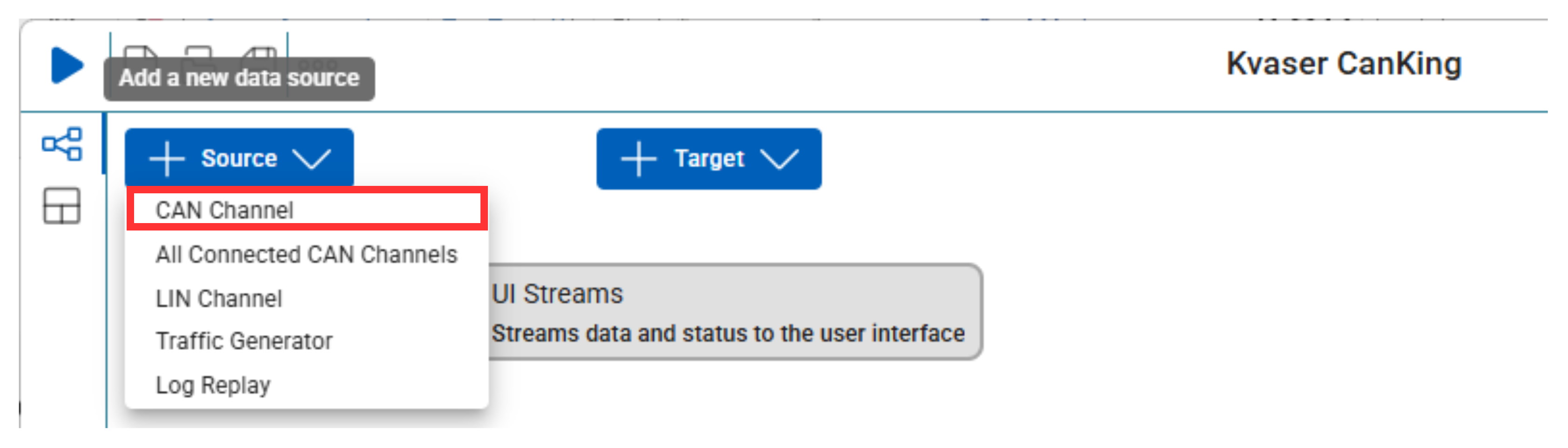
- In the Source menu, select CAN channel.
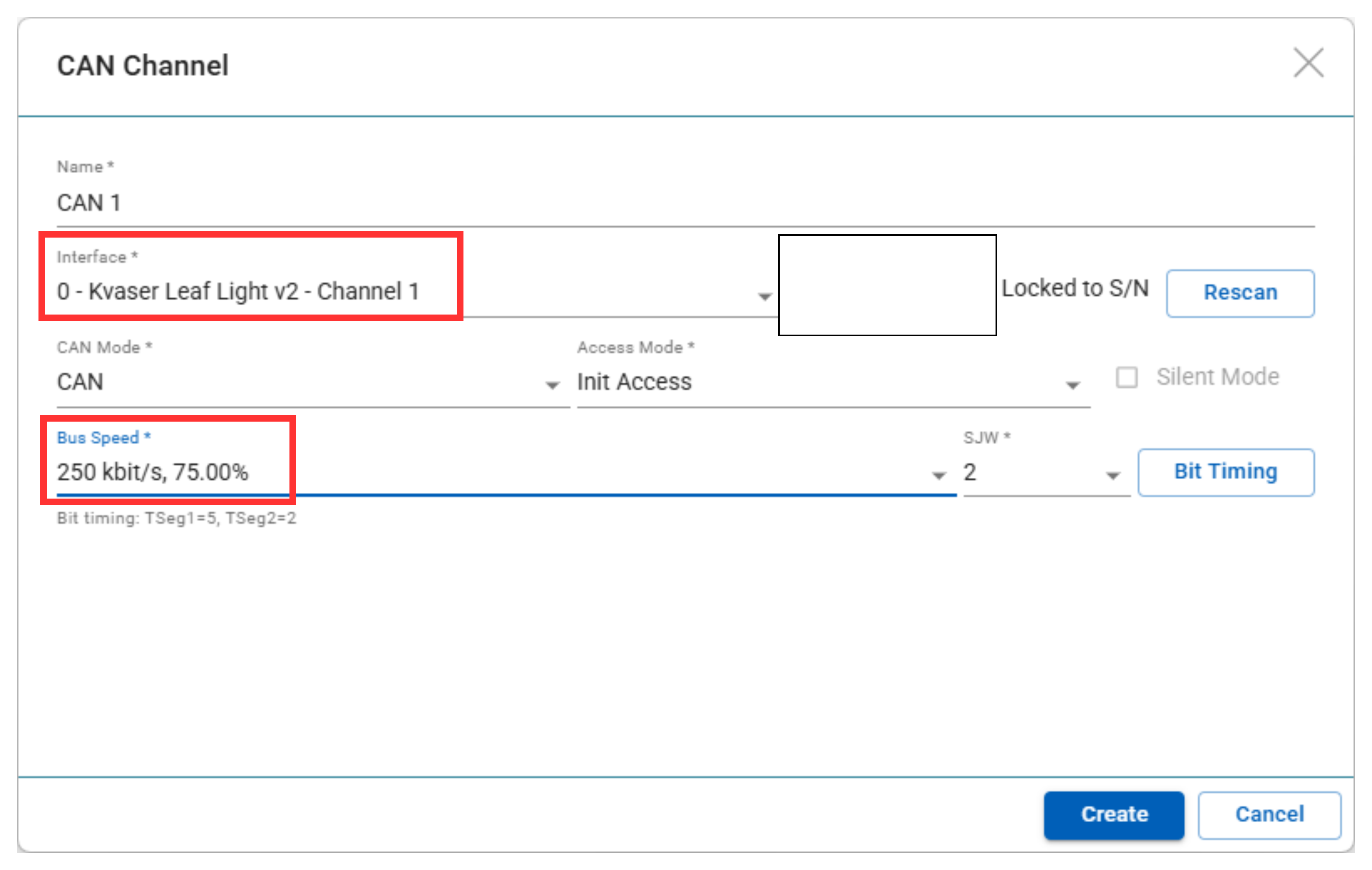
- If the driver is installed correctly and the device is connected, the software identifies the interface model automatically. Name the channel and select the bus speed configured in WS-CAN-TOOL — 250 kbit/s for this application — then create the channel.
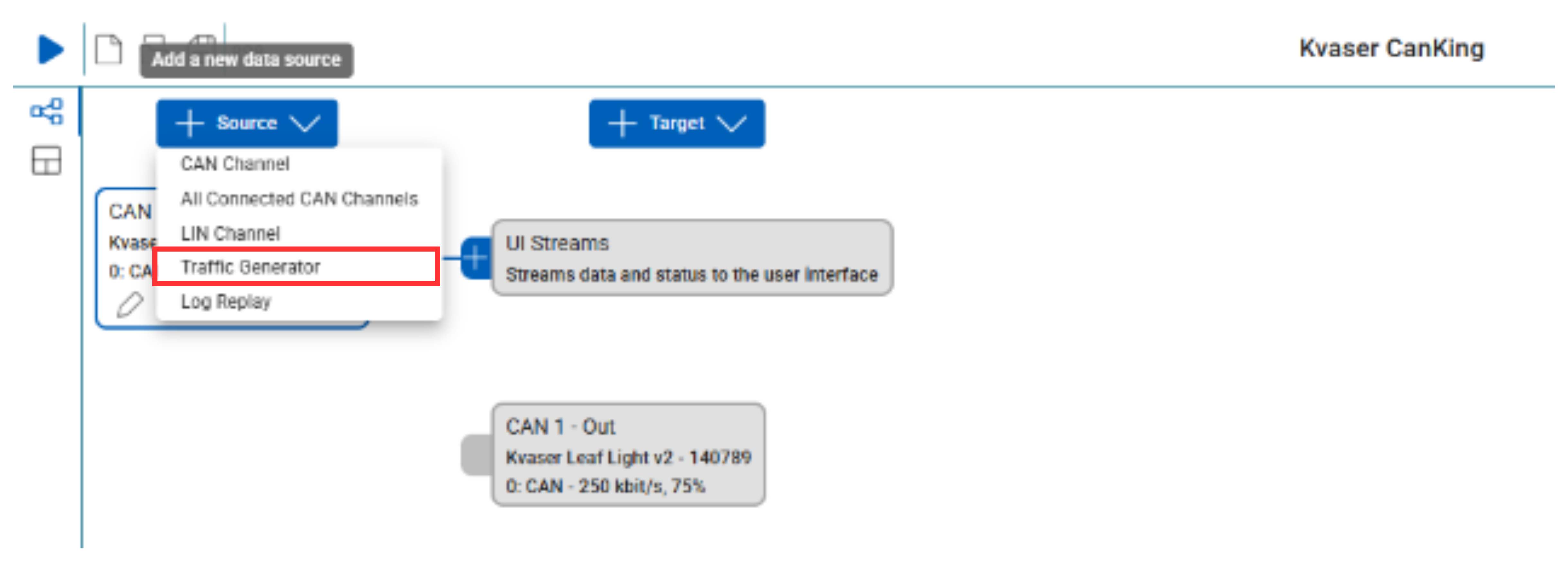
- Create a Traffic Generator block in the Source menu.
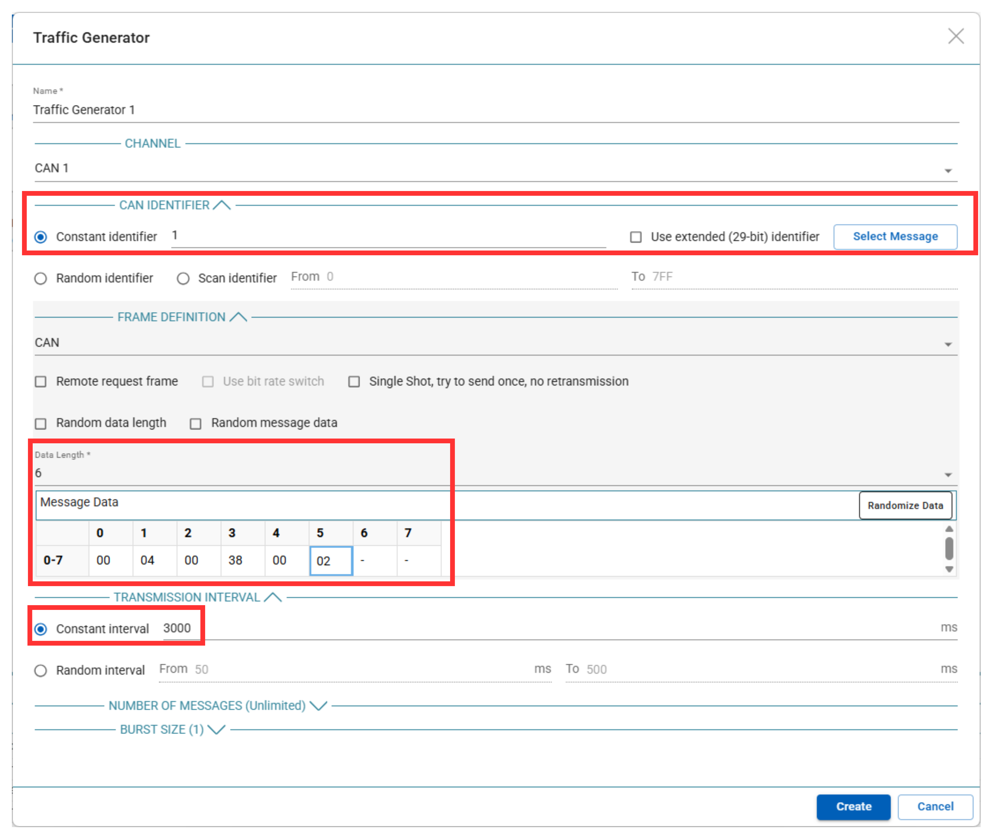
- Configure the CAN parameters as follows:
- Constant Identifier: enter the CAN ID value set in WS-CAN-TOOL.
- Interval: 3000 ms for this application (user-editable).
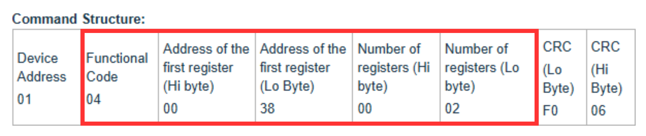
- Data Length: 6 bytes. The software doesn't need the CRC bytes used in the Modbus RTU Command and Response Examples article, since the temperature median value is being requested here.
- First Byte: 00, not 01 — the Modbus conversion mode treats this first byte as an indicator of whether the message is segmented, not as a device address.
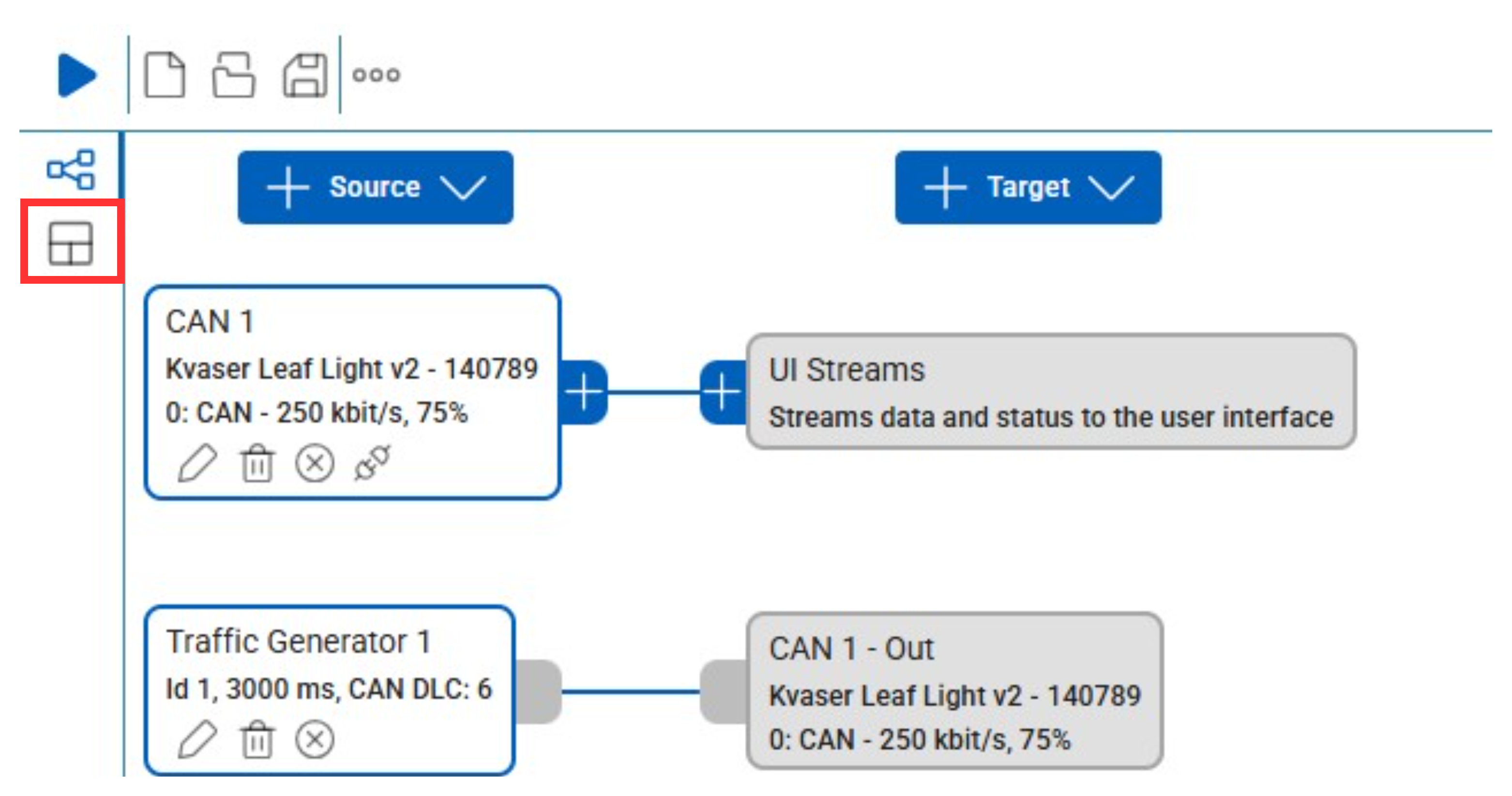
- Create a Workspace to view the sent and received data.
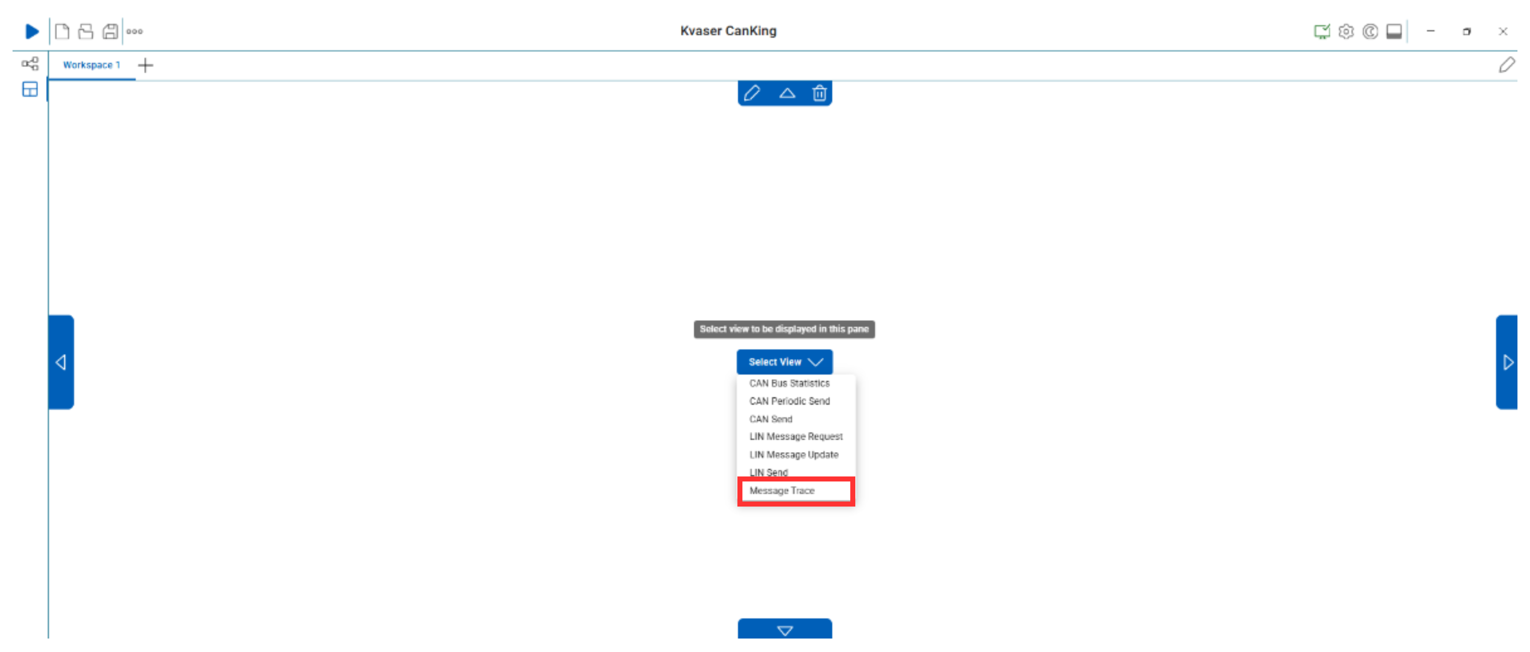
- In the Select View menu, click Message Trace.
3.2 Connection with RS232/485/422-to-CAN Converter
Using the wiring diagram below, connect the DB9 port to the converter.
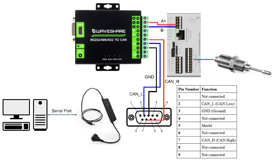
4. Rheonics SME Data Integration
Once all devices are connected and configured, click the Start button to begin communication with the SME. Data received in CanKing appears in HEX format, so it must be converted before comparing it with RCP measurements.
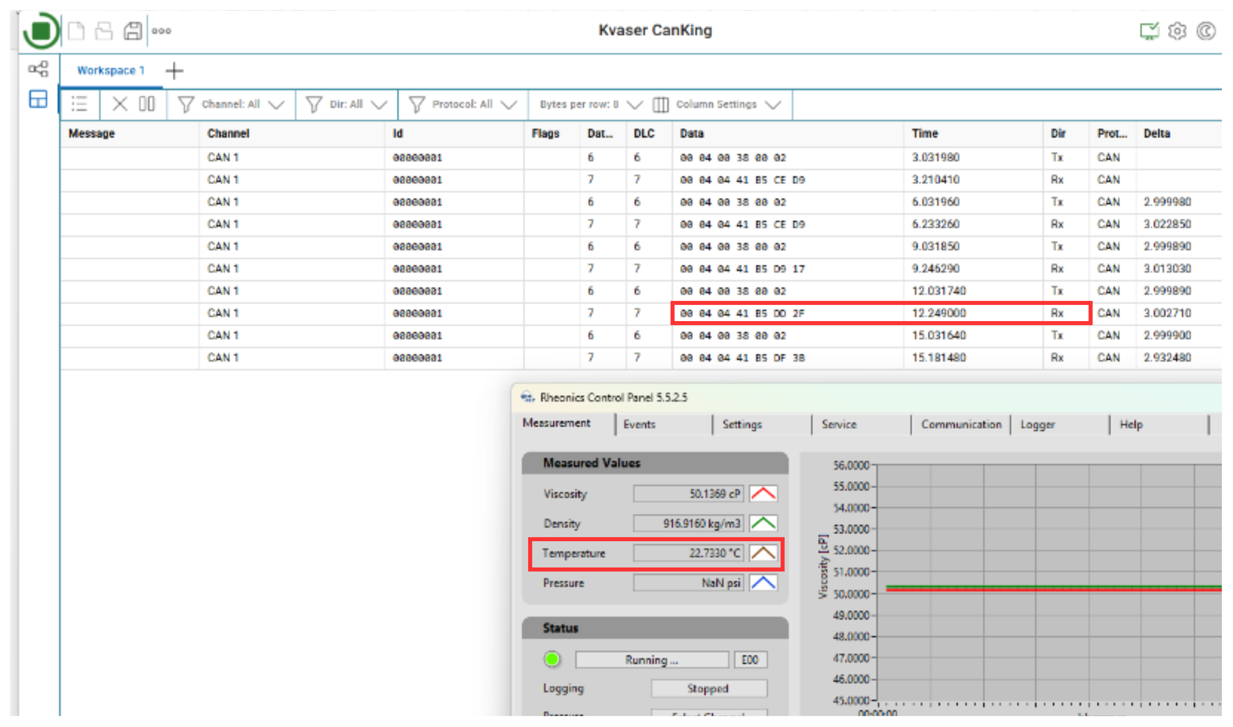
After conversion, the hexadecimal value 0x4185002F (last 4 bytes) equals 22.73 in decimal — confirming the data was requested and transmitted successfully, with no communication or conversion errors. This process can be tested with different parameters and registers, as described in Modbus Input Registers.
| Still have questions about integrating your Rheonics SME with a CAN network? Contact Rheonics Support for further assistance. |
Further information
Modbus Communication
- Modbus Organization partnership with Rheonics — background on Rheonics' involvement with the Modbus Organization and RTU protocol standards.
- Connecting Modbus RTU (RS-485) outputs — step-by-step wiring guide for enabling Modbus RTU communication on Rheonics sensors.
- Modbus Input Registers — complete list of Modbus input registers available on Rheonics SME devices.
- Modbus RTU Command and Response Examples — example Modbus RTU command/response byte sequences for reading SME data.
5. References
- [1] Waveshare — WS-CAN-TOOL download
- [2] Kvaser — Driver and CanKing software download
- [3] National Instruments — Controller Area Network (CAN) Overview
- [4] CSS Electronics — CAN Bus: Simple Intro Tutorial
- [5] Kvaser — CAN Protocol Tutorial
- [6] Waveshare — RS232/485/422 TO CAN Wiki