
What Rheonics products are involved? What is this article helpful for? |
Proper grounding is critical for measurement accuracy, electrical safety, and long-term instrument reliability. Poor or missing grounding is one of the most common causes of signal noise and measurement instability.
1. Overview
The external grounding tab must be connected to the control cabinet ground or the facility earthing system. This connection establishes an equipotential reference between the SME-TR/SME-TR(D) housing, the control cabinet, and other bonded metallic structures, thereby reducing the risk of ground loops and minimising the effects of electromagnetic interference (EMI).
For optimal performance, the grounding conductor connected to the external grounding tab should be as short as possible and routed directly to the main grounding point of the control cabinet. The use of a low-impedance conductor with an appropriate cross-sectional area, in accordance with local regulations and standards, is strongly recommended.
Figure 1 shows the external grounding terminal connected to the plant grounding point.
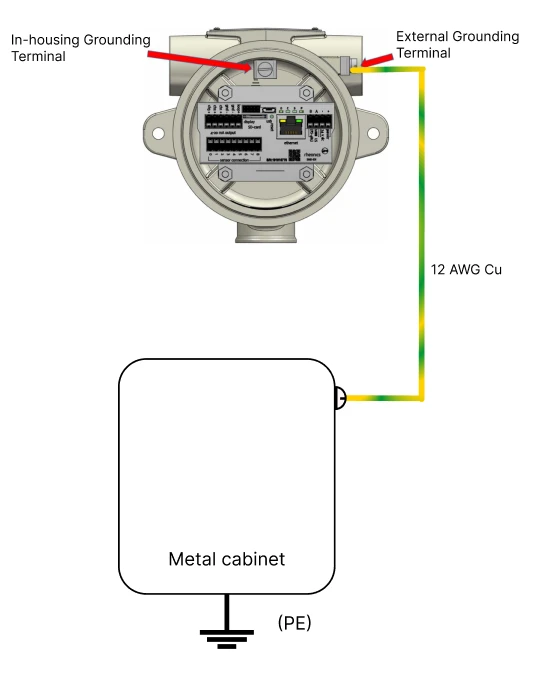 | 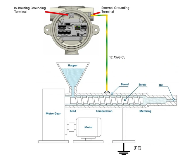 |
Figure 1 — PE grounding installation examples: cabinet PE bar (left) and extrusion machine chassis (right)
2. Grounding Cable Specification
| Parameter | Requirement |
|---|---|
| Minimum wire gauge | 12 AWG (3.3 mm²) for instrumentation grounding applications |
| Conductor material | Copper — stranded or solid. Do not use aluminium for instrumentation grounds. |
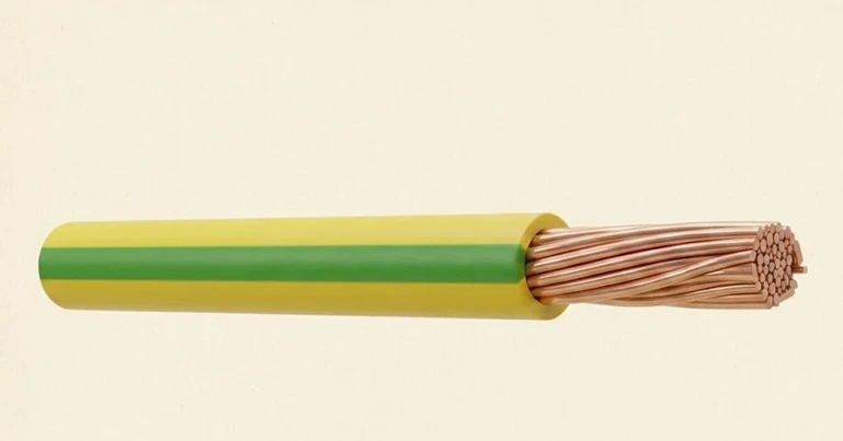
| Insulation / colour | Green/yellow striped (standard PE identification) recommended |
| Run length | As short as possible — minimises impedance and EMI susceptibility |
| Connection quality | Low-impedance, solid mechanical contact. No paint, rust, or oxidation at termination point. |
3. Connection Points
3.1. Instrument Side
- External grounding screw or stud on the instrument enclosure (see label on housing)
- Internal ground terminal inside the transmitter head (where accessible)
- SME terminal Pin 0 (green/yellow wire) — chassis/signal ground
- Cable shield/drain wire connected at the instrument cable gland or connector shell
Below is the wiring diagram, including all grounding connections. It is very important to review this during commissioning to ensure proper sensor performance.
Wiring — Variant A
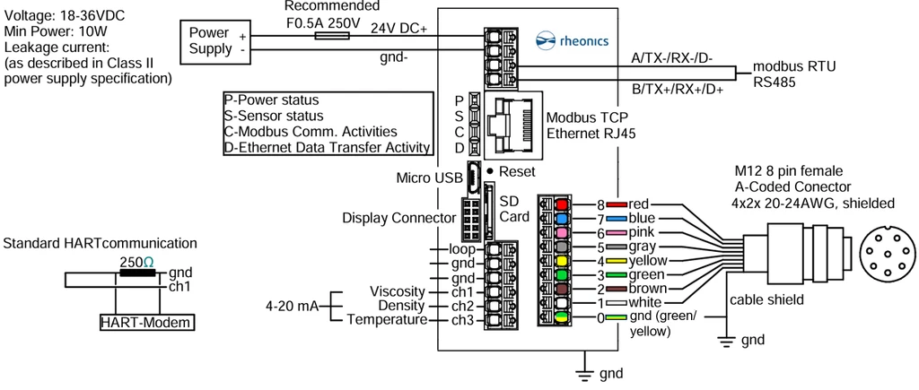 Figure 2 — SME wiring, Variant A
Wiring — Variant B
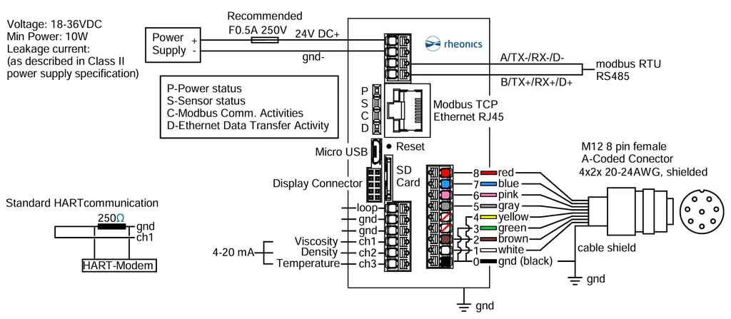 Figure 3 — SME wiring, Variant B
Variant C uses the same schematic as Variant A, but the grounding is made inside the SME-TR(D) housing using the in-housing grounding terminal. This connection provides a defined reference for signal grounding and supports stable operation of the SME electronics. Variant D uses the same schematic as Variant B, but the grounding is likewise made inside the SME-TR/SME-TR(D) housing using the in-housing grounding terminal; the external grounding of the SME-TR/SME-TR(D) is then connected to the plant-side grounding.
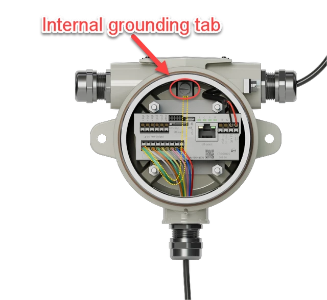 | 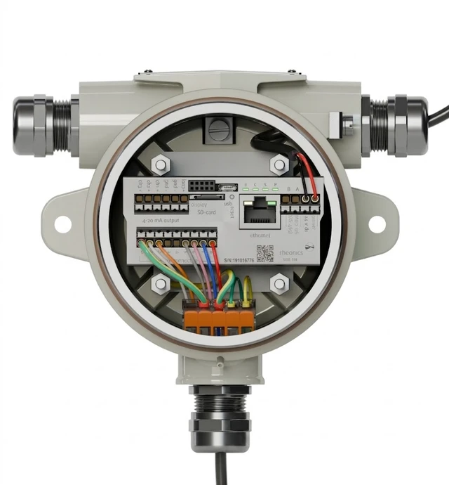 |
Figure 4 — SME-TR(D) internal wiring, Variants C and D
3.2. Plant Side
- Plant Protective Earth (PE) rail or properly earthed metal structure
- Ground bar within local junction box, bonded to panel ground bar
- Main panel ground bus bar in the control room
- Cable shield/drain: connect the cable shield to ground at both ends. On the electronics side, the shield is grounded through a direct connection. On the sensor side, the shield is grounded through the sensor housing. Since the sensor housing is metallic, the sensor must also be grounded through the installation — typically via a grounded metal pipe, holder, or mounting structure. Ensure that the pipe, holder, or mounting hardware provides a reliable ground connection to the sensor housing.
3.3. M12 8-Pin Connector — Conductor Reference
| Conductor |
|---|
| Pin 0 — Green/Yellow to ground |
| Pin 1 — White |
| Pin 2 — Brown |
| Pin 3 — Green |
| Pin 4 — Yellow |
| Pin 5 — Gray |
| Pin 6 — Pink |
| Pin 7 — Blue |
| Pin 8 — Red |
| Cable Shield — Always to ground |
| Refer to the wiring diagram shipped with the instrument, or to the Rheonics SME Installation Manual, for your specific variant. The green/yellow Pin 0 is always the primary protective earth conductor. |
4. Installation Examples
| Configuration | Description |
|---|---|
| Direct instrument-to-earth | 12 AWG copper from instrument enclosure ground screw to local plant earth stake or bonded structural steelwork |
| Via junction box | Instrument ground to junction box ground bar; junction box ground bar to panel ground bar via 12 AWG or larger |
| Shield termination | M12 cable drain wire run through conduit, terminated at the control panel ground rail — instrument end left floating |
| Bracket bonding | SME transmitter housing bonded to mounting bracket; bracket connected to plant PE via 12 AWG cable to structural steel |
5. Post-Installation Verification
After completing grounding connections, verify the installation using a standard multimeter before commissioning the instrument.
- Continuity check — set the multimeter to continuity/beep mode. Probe between the electronics/probe ground point and the plant earth. A continuous beep confirms a solid low-resistance path.
- Resistance measurement — measure resistance between grounding points. Values should be <1 Ω. Readings above a few ohms indicate a poor termination or corroded contact.
- Visual inspection of termination — confirm bare metal contact is visible under the lug or ring terminal. No paint, rust, anodising, or gasket material should be trapped between the conductor and the mating surface.
- No floating ground — verify that no grounding conductor is left disconnected at either end. A floating ground provides no protection and can act as an antenna for radiated EMI.
6. How to Reduce EMI Effects
To reduce the impact of EMI, we recommend the following:
- Ensure the proper grounding of the panel (where the sensor electronics are mounted) to the equipment ground (where the sensor probe is mounted).
- Ensure that the sensor (probe and electronics) is properly grounded.
- Ensure the sensor cable shield is properly connected to ground.
- Connect all ground connections to a metallic common ground block.
- Verify that all electronic components are adequately earth-grounded.
- Maintain separation between power lines and the sensor cable to prevent interference.
- In extreme cases, an EMI filter is also recommended.