
What products are involved?
DVM – Density and Viscosity Sensor Unit | Other Rheonics inline sensors with NPT or G (BSPP) threaded process connections (e.g., SRD, SRV), e.g., Variants -X1 -X5 -X8.
What is the purpose of this article?
This article is a guideline for using a torque wrench correctly with Rheonics sensors, using the DVM's sensor retaining screw as the main worked example. It also briefly covers NPT and G-threaded connections used on other Rheonics sensors, and how to choose between analog and digital torque wrenches.
| Short answer: Always apply installation force through the process-connection body/hex — never through the probe — and stop exactly at the specified torque or turn count (e.g., 20 Nm for the DVM sensor retaining screw). Never use a torque wrench to loosen fittings, and never use impact or power tools. |
TABLE OF CONTENTS
- 1. Overview
- 2. Before you install
- 3. Installation procedure
- 4. Types of torque wrenches
- 5. Avoiding probe damage
- 6. Recommendations
1. Overview
A torque wrench exists to apply a known, repeatable amount of force to a fastener, enough to seat and seal the joint, but not so much that it damages the threads, the sealing surface, or the part itself. Using a torque wrench correctly matters more than it might seem: too little torque leaves a joint loose or leaking, too much can crack a port, strip threads, or transmit stress into a sensor's internal components.
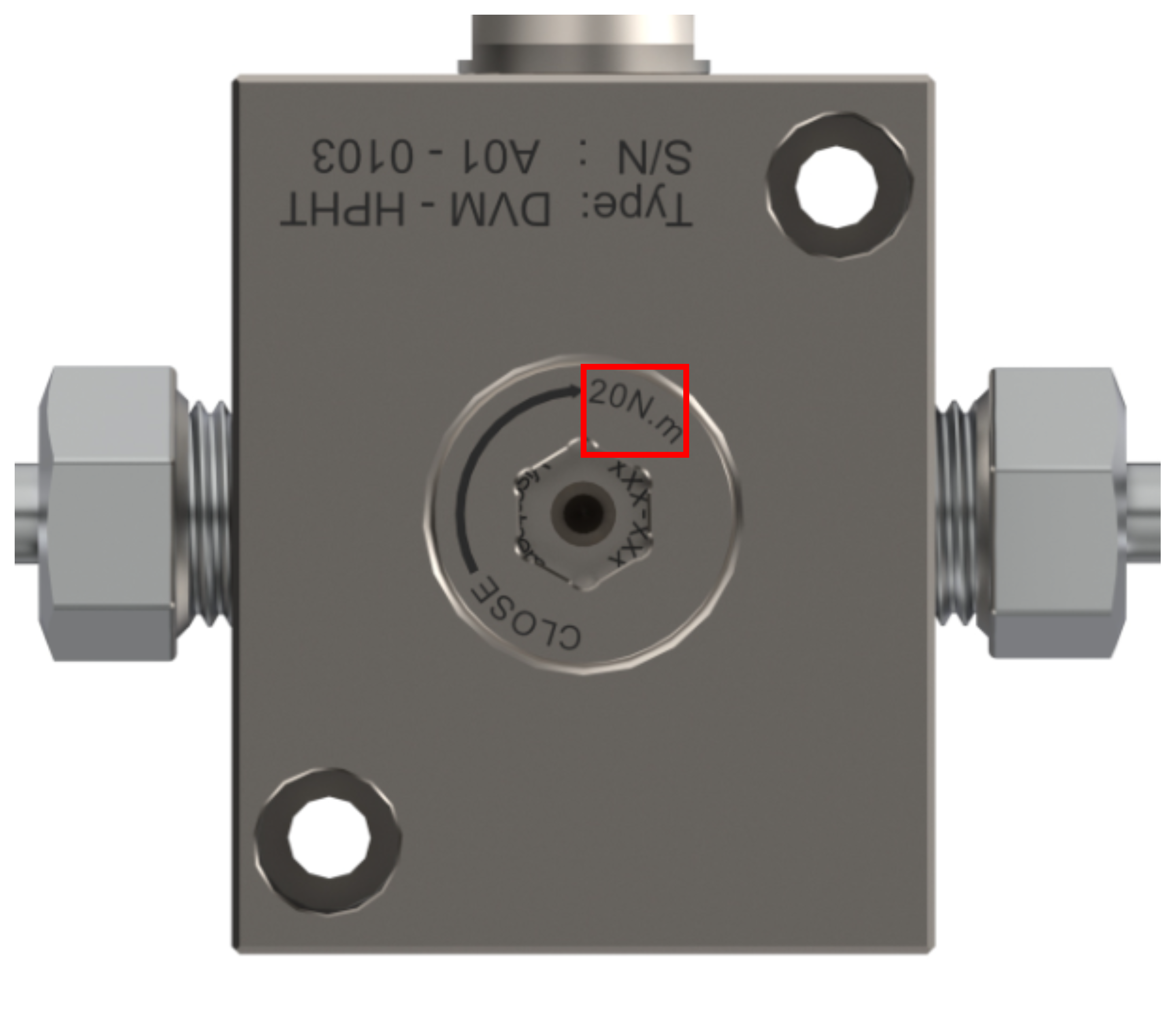
This article uses the Rheonics DVM's sensor retaining screw as the main worked example, since it's the most common torque-wrench task Rheonics customers perform, and it has a specified value in the DVM Operator Manual.
2. Before you install
2.1 Tools and materials
- A torque wrench (analog or digital; ratchet or adjustable head) rated for the required torque range, with the correct socket or crowfoot adapter for the fitting.
- A clean, lint-free cloth to wipe down threads before assembly.
- Protective gloves: stainless steel fittings can have sharp thread crests, and sealants/anti-seize compounds should not contact skin directly.
| ⚠ Important — SRV/SRD probe body: Never use the sensor's probe body as a lever or handle point to thread the probe into place. All installation force must be applied through the process-connection body/hex, not the probe. |
3. Installation procedure
3.1 DV sensor retaining screw (DVM maintenance)
The DVM ships with the DV sensor already installed. This procedure is only needed when the sensor must be removed for cleaning or maintenance.
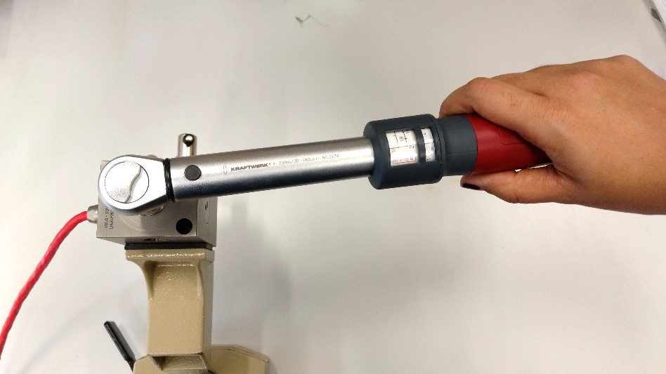
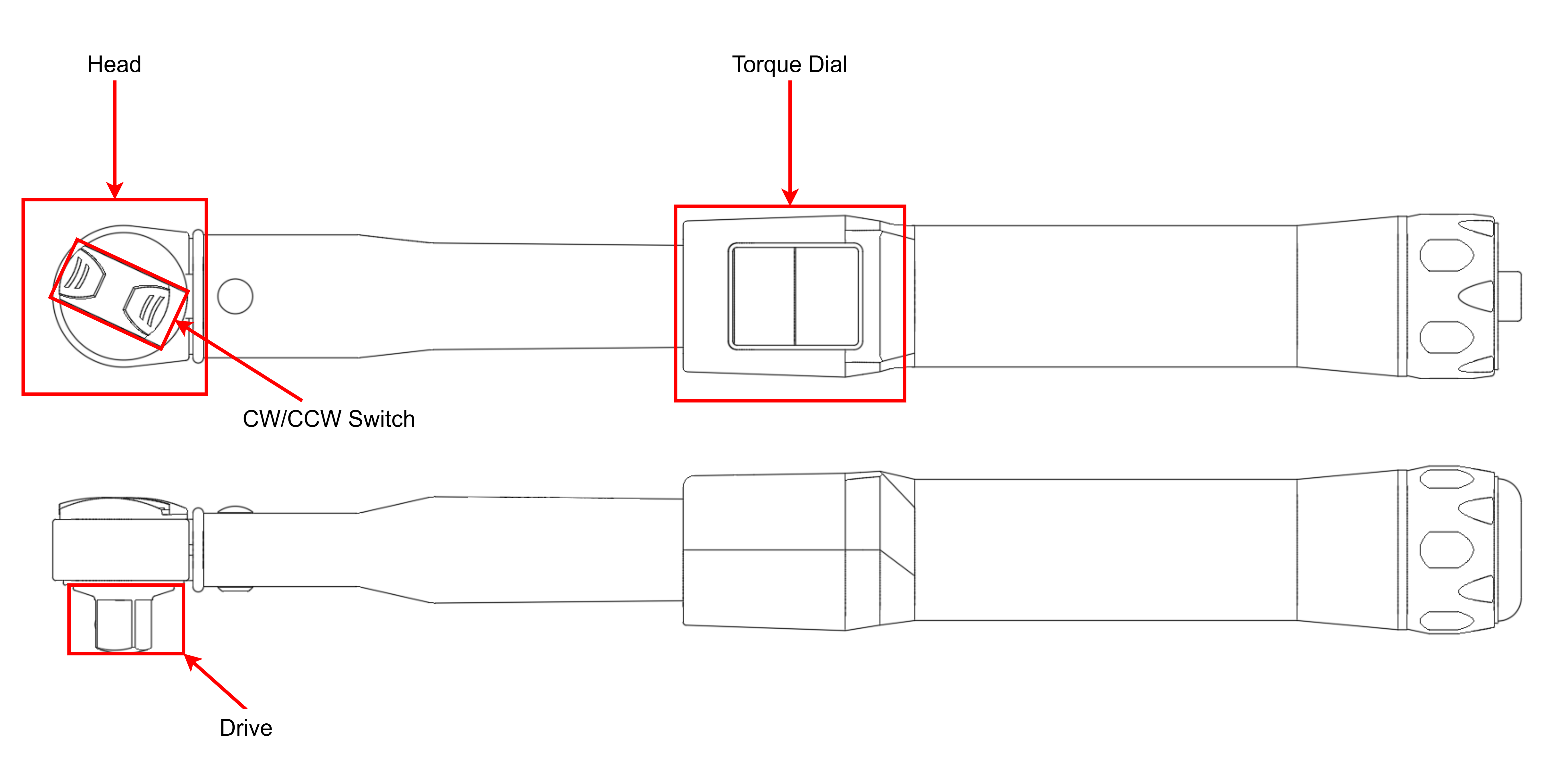
- Set the torque wrench (TOW-DVM) to 20 Nm and fit the wrench's drive to the sensor retaining screw on the DVM module. Be sure the CW/CCW switch in the wrench's head is selected for counter-clockwise mode.
- Remove the retaining screw. This exposes the back of the DV sensor and its M4 threaded removal/insertion hole. Use the tool to loosen the knob until it's possible to do it manually, then switch to clockwise mode and turn the wrench's drive with your fingers.
- It is recommended to hold the DVM body in a bench vise to apply the necessary torque. Use soft jaw covers in the vise to avoid marring the module. This also applies to threading in the inlet and outlet fittings.
- Thread the sensor insertion and removal tool (ERT-DVM) finger-tight into the back of the DV sensor, then use it to back the sensor out of the module.
- For O-ring/backup ring replacement, follow the ORT tool procedure in the DVM Operator Manual (Section 6.3–6.4).
- To reinstall, reverse the process and retorque the retaining screw to 20 Nm with the same wrench in clockwise orientation. A mechanical click indicates the defined torque has been achieved.
A reference video walking through this procedure is available — see [1] in the References section below.
3.2 NPT and G threaded sensors
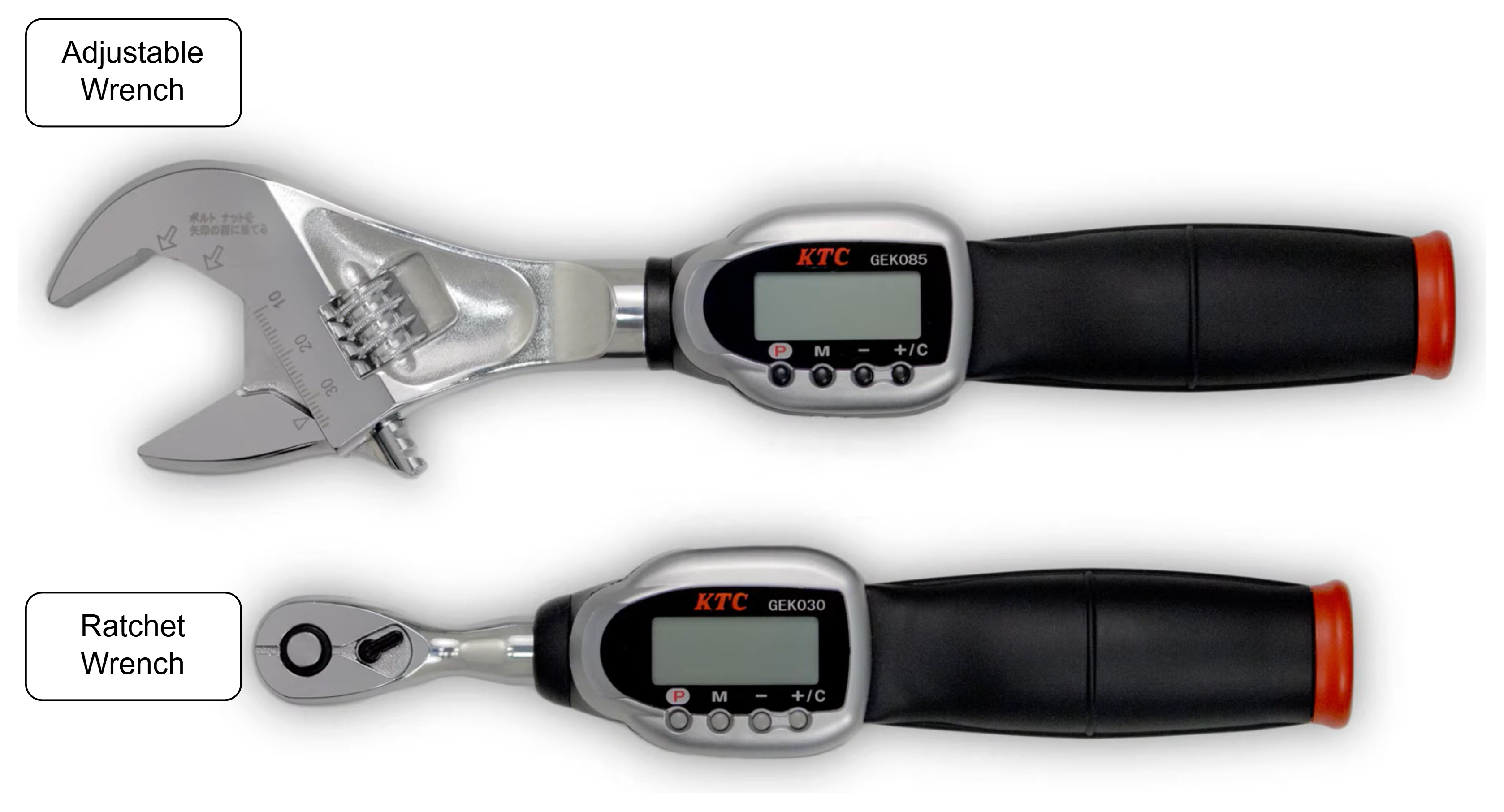
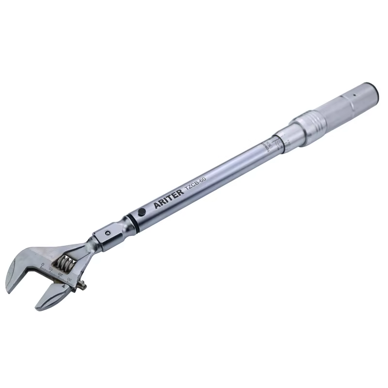
Some Rheonics sensors (e.g., SRD, SRV) connect to process piping through NPT or G threads, and a torque wrench can also be used here. The installation and use of the tool follow the same instructions, but the main consideration is to have the proper wrench head for the hex body of the sensor, for example, an adjustable head.
| Connection | Spec type | Value |
|---|---|---|
| DV sensor retaining screw (inside DVM module) | Fixed torque | 20 Nm |
| G-threaded sensor | Fixed torque | 18 Nm |
| NPT-threaded sensor | Turns past Finger Tight (TPFT) | 2–3 turns |
Table 1. Defined adjustment for Rheonics sensor connections.
4. Types of torque wrenches
Apart from the head type, there are two main types of torque wrenches based on their inner mechanism. The main difference is how the user sets the torque: in an analog or digital way, but both serve the same purpose, so either can be used as an alternative for an installation task.
4.1 Analog torque wrenches
Analog wrenches set a fixed torque with an internal spring and a calibrated dial. Select the tightening direction with the directional switch, then tighten until a click confirms the set torque has been reached.
4.1.1 Examples
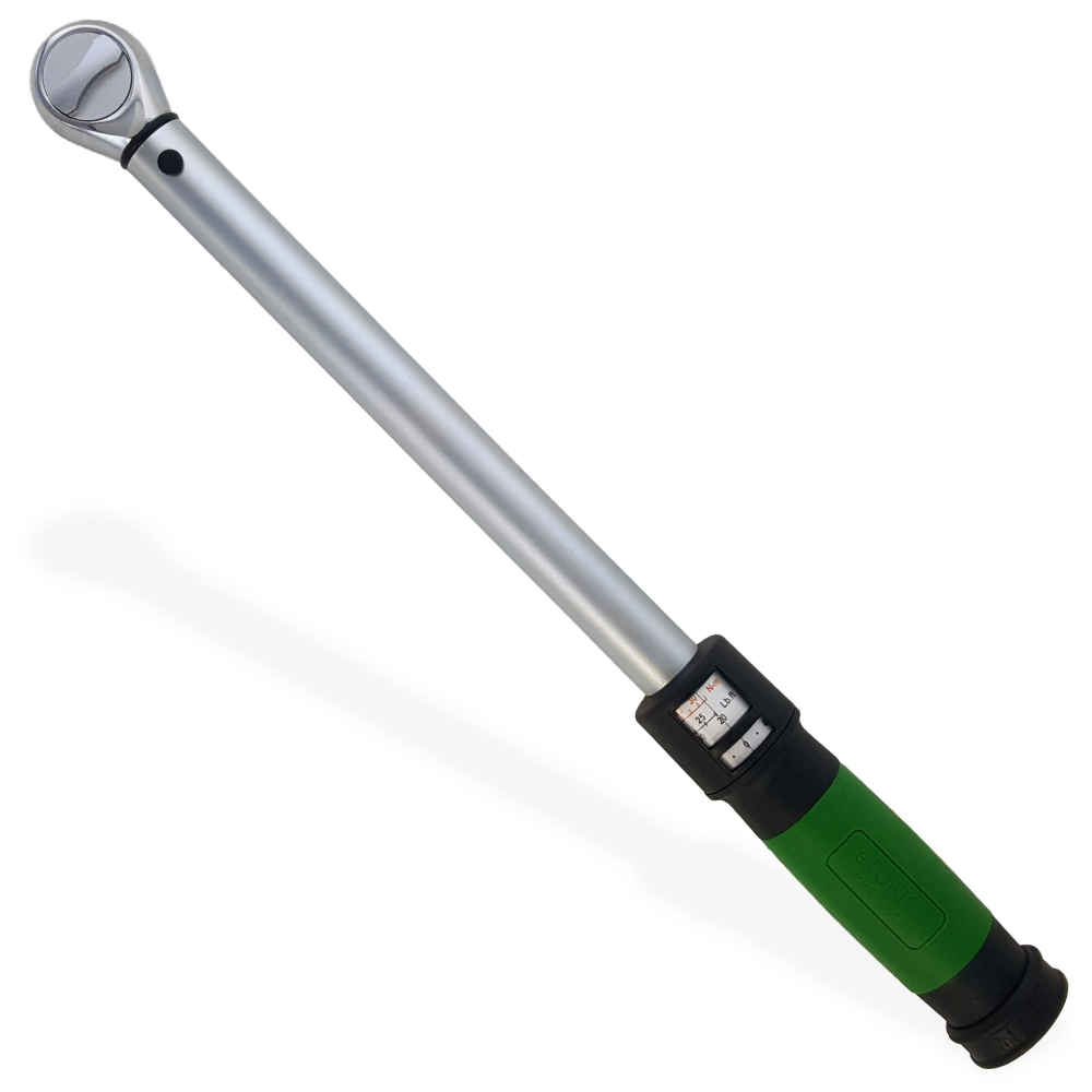
Figure 5: eTORK Torque Wrench
4.2 Digital torque wrench
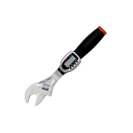
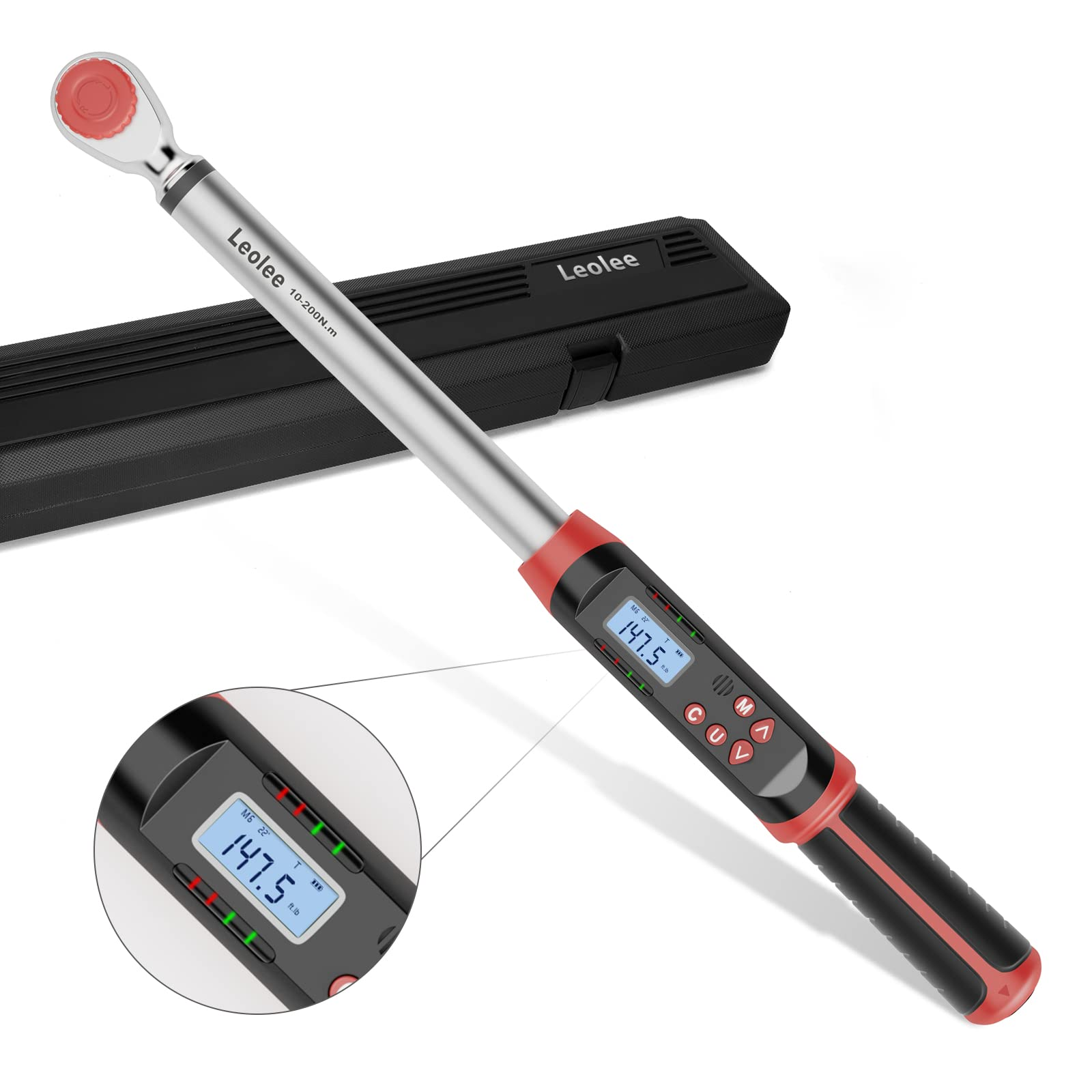
Since they are digital, these wrenches have a display that lets you set the target torque and select the units, as well as monitor the torque being applied during use. Depending on the model, an LED indicator, an audible alarm, or a vibration will alert you when the target torque is reached.
4.2.1 Examples
5. Avoiding probe damage
| Mistake | Consequence | How to avoid it |
|---|---|---|
| Cross-threading and forcing the connection | Thread damage, sensor sits misaligned, probe contacts port wall | Back out and re-align if hand-threading doesn't turn smoothly |
| Over-torquing past the specified value | Stress transmitted through the body into the probe mount; thread or port damage | Stop exactly at the specified torque or turn count. Never add "extra" for safety. |
| Impact wrenches or power tools | Rapid over-tightening, galling, or uncontrolled shock load to the probe | Use hand torque wrenches only — controlled hand tools reduce the excess torque and heat that drive galling and shock damage |
Table 2. Common mistakes and how to avoid probe damage.
6. Recommendations
- Be clear about the torque range you will be working with, and choose a tool that achieves that range and uses the required units from the manual — or do the mathematical conversions.
- Do not use a torque wrench to loosen fittings. This damages the tool, especially analog ones.
- Keep the tool protected at all times. A dropped or knocked wrench has a high risk of going out of calibration.
- For analog tools, release the internal spring by setting the dial back to 0 after use. Leaving the spring compressed for long periods damages the internal mechanism and, as a result, the tool's accuracy.
- For installation, we recommend using official Rheonics weldolets when available for your application.
Further information
DVM maintenance
- DVM Operator Manual — full sensor removal, O-ring/backup ring replacement, and calibration procedures.
Sensor installation
- SRV/SRD Process Connection Guide — NPT and G-thread mounting requirements for inline sensors.
References
- [1] Rheonics DVM sensor retaining screw procedure — reference video — youtube.com/watch?v=Eo5IL0i9ExQ