
What products are involved?
SRV – Inline Viscosity Meter | SRD – Inline Density & Viscosity Meter | SME Electronics
What is the purpose of this article?
This article explains how to wire and configure the 4-20 mA analog output from a Rheonics sensor's SME electronics into a Mitsubishi MELSEC PLC (FX3U and FX5 series), covering PLC-side wiring, the Rheonics control panel settings, and the PLC-side ladder programming needed to read and scale the signal into an engineering unit (e.g., viscosity or temperature).
TABLE OF CONTENTS
1. Getting Started
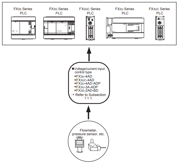
This guide uses the MELSEC-F/FX line as the reference platform because it is Mitsubishi's introductory, most cost-effective series and one of the first MELSEC lines still in production. The wiring and scaling principles shown here also apply to other MELSEC lines that use an analog input module in current mode. The example uses the FX3U-4AD expansion module, the most basic analog input expansion available for the FX3U series.
2. PLC Wiring
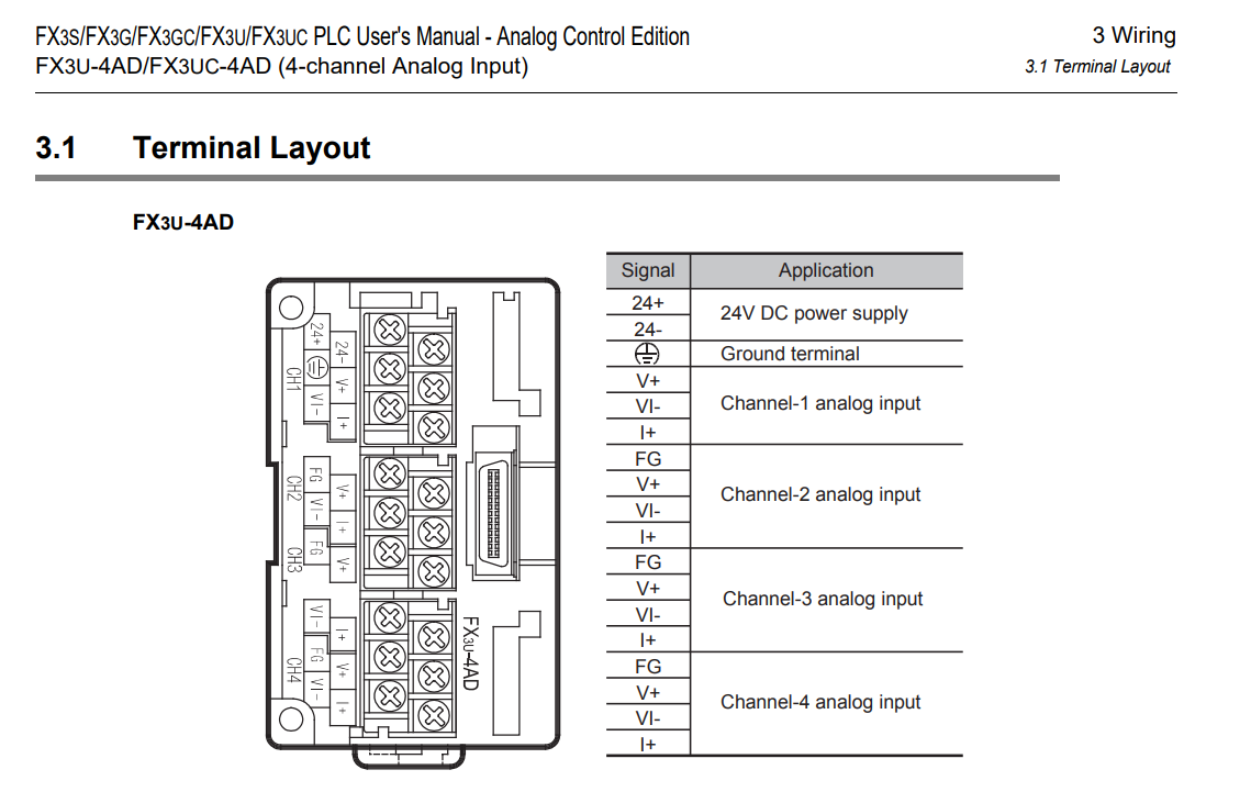
2.1 MELSEC Analog input guidelines - terminal layout
Before wiring, identify the terminal layout for the analog input module you are using. Terminal numbering and channel assignment vary by model, so always confirm with the module's own manual before connecting field wiring.
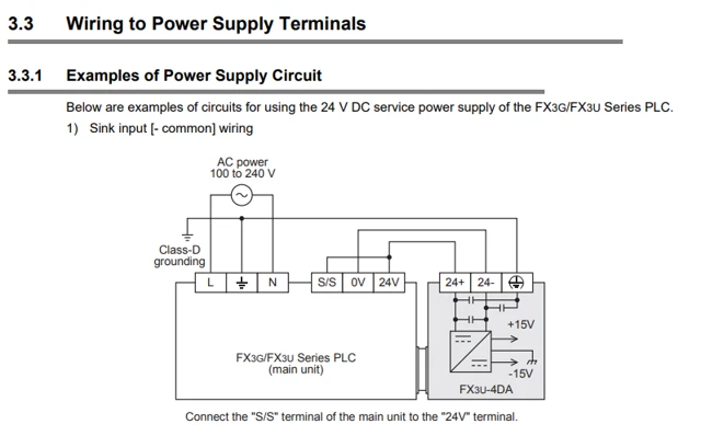
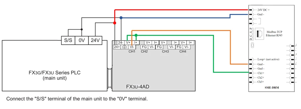
2.2 Important wiring for sink input
| ⚠ Important — sink wiring: To operate the module as a sink input, the S/S terminal must be connected to the 24 V terminal on the main PLC unit. Confirming this jumper before powering the loop avoids miswired current-loop faults. |
2.3 General connection schematic
When connecting the SME electronics' 4-20 mA output, the corresponding analog input channel on the MELSEC module must be configured for current input mode, not voltage mode.
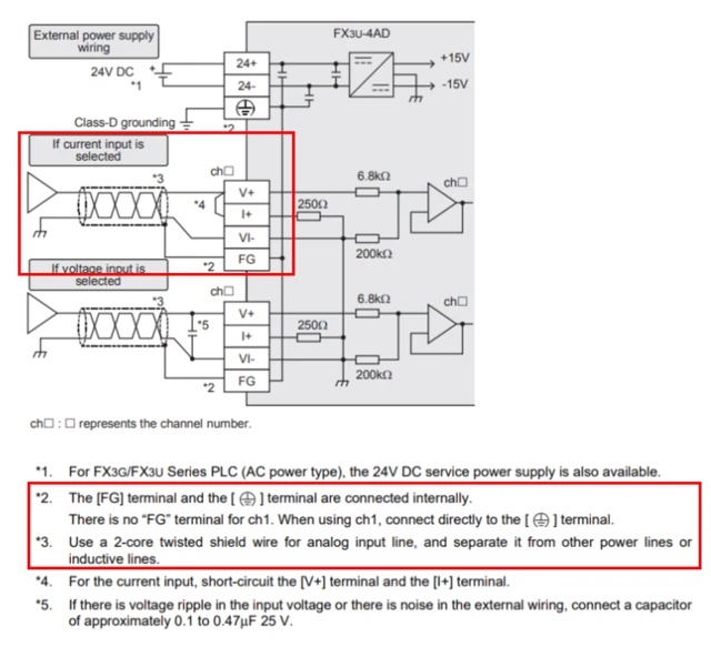
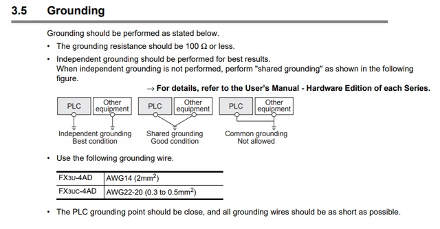
2.4 Grounding
Follow the module's grounding guidelines for the analog input terminals to keep the 4-20 mA signal free of induced noise (Figure 5). The complete signal wiring, including grounding, should match the diagram in Figure 6.
3. Rheonics control panel settings
| → See: Analog Signal Integration with Micro820 — Section 3, Rheonics control panel settings. The SME electronics' analog output configuration (4-20 mA range, output assignment) is identical regardless of the PLC brand connected, so the same steps apply here. |
4. PLC setup
4.1 Mitsubishi software
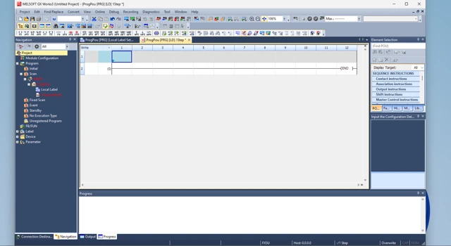
Mitsubishi's PLC programming software is not free, but a demo version is available. Note that the GX Works3 demo supports the FX5 series but does not support the FX3 line. For FX3U programming, use GX Works2 instead.
4.2 Instructions for FX5 series
Requirements: GX Works3, FX5 series CPU, and an analog input block (built-in or expansion).
- Create a new Project in GX Works3 for your FX5 CPU model.
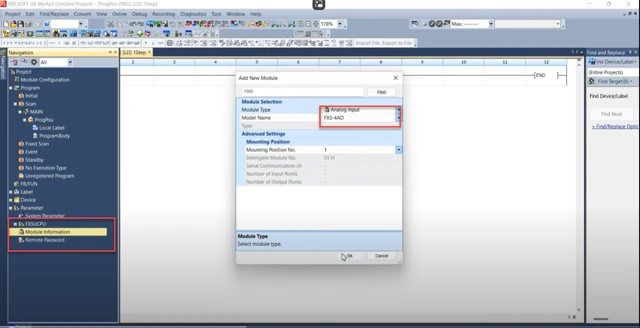
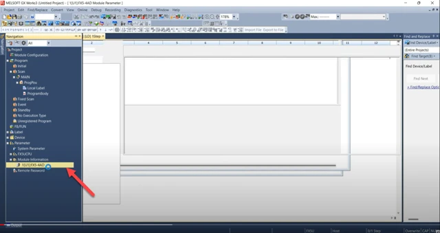
- Add the analog module. In the Navigation Panel, select the CPU. Right-click on Module information → Add New Module, and add the module matching your model name.
- Open the module. Double-click the newly added module in the Navigation panel to open its configuration.
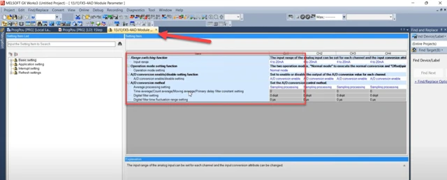
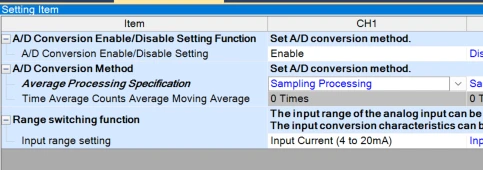
- Configure the channel settings under Basic Settings.
| Item | Setting name | Value |
|---|---|---|
| Channel | CH1 | CH1 |
| A/D Conversion Enable/Disable | Disable / Enable Setting | Enable |
| A/D Conversion Method | Set A/D Conversion method | Sampling Processing |
| Range switching function | Input range | Input Current (4 to 20mA) |
Table 1: Basic Settings
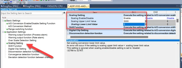
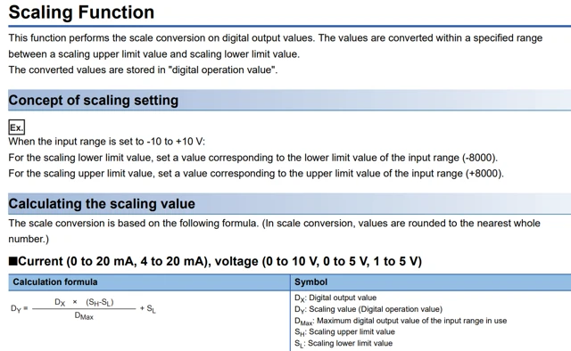
- Configure Application Settings - Scaling. The FX5 module includes built-in scaling, so the read value can be converted to your engineering unit without additional program blocks. Figure 12 gives an example of scaling the input for viscosity.
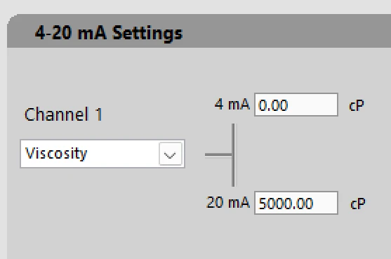
| Item | Value |
|---|---|
| Scaling enable/Disable | Enable |
| Scaling Upper Limit | 5000 |
| Scaling Lower Limit | 0 |
Table 2: Application Settings
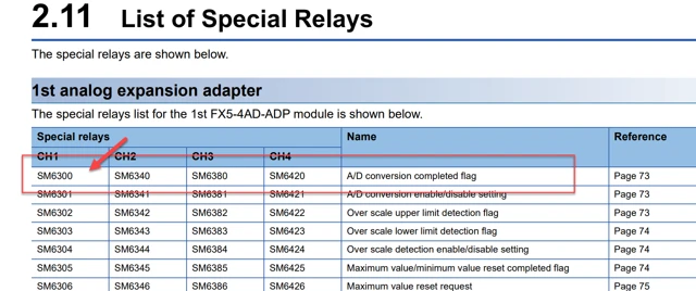
- Finding the register (special device) for the input channel. Use the intelligent function module reference or the module's manual to identify the assigned SM and SD registers for the channel.
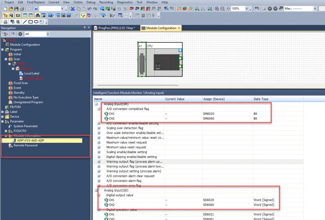
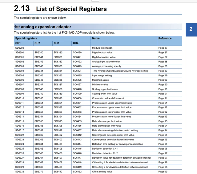
- Move the register value into a data register. Use the
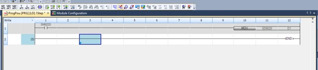
SM6300special memory bit as the enable condition. Then use aMOVinstruction to move theSM6030scaled value into a data register, e.g.,D1.
Further information
PLC Integration
- Analog Signal Integration with Micro820 — wiring and PLC-side setup for the Micro820, including the Rheonics control panel settings referenced in Section 3.
- Rheonics Sensor Output: Analog Signal (4-20 mA) Integration with LOGO! Siemens PLC — the same wiring and scaling approach applied to a Siemens LOGO! PLC.
- How to Diagnose and Fix Your 4-20mA Channel Output Data Inconsistency — troubleshooting steps if the PLC-side reading doesn't match the sensor output.
4-20 mA & RCP configuration
- Connecting 4-20 mA Outputs — background on the SME's self-powered 4-20 mA current loop and 4-wire transmitter wiring.
- Analog Signals Setup with the RCP — how to set the 4-20 mA upper/lower limits and assign a measurement parameter to each channel in the Rheonics Control Panel.
Products
- SRV – Inline Viscosity Meter — product page and technical specifications.
- SRD – Inline Density & Viscosity Meter — product page and technical specifications.
- SME Electronics — overview of the sensor electronics module and its analog/digital output options.
References
- [1] Mitsubishi Electric — FX3S/FX3G/FX3GC/FX3U/FX3UC Series User's Manual, Analog Control Edition: PDF
- [2] Mitsubishi Electric — FX3U Series User's Manual, Hardware Edition: PDF
- [3] Mitsubishi Electric — FX PLC Main Unit product page: Link
- [4] Mitsubishi Electric — FX Analog Expansions product page: Link