
What Rheonics products are involved? This article covers the Rheonics SME (Smart Module Electronics), the sensor electronics used on the SRV, SRD, DVP and DVM instruments. All SME devices implement a Modbus RTU slave natively — no protocol gateway or data concentrator is required. What is this article helpful for? This article shows how to wire a Rheonics SME to a Honeywell Enraf CIU 888 tank gauging platform over Modbus RTU (RS-485), configure the CIU 888 field port and Modbus device mapping in CIU 888 Service Tool, and bring Density, Viscosity, Temperature and Sensor Status into CIU 888 as scanned tank parameters. |
1. Overview
The CIU 888's Serial Modbus Card acts as a Modbus RTU master (client) on its field ports. The SME sits on the field port as a native Modbus RTU slave; the CIU 888 then makes the scanned values available to host systems (Entis, Experion, SCADA, etc.) over Modbus TCP/IP or OPC UA TCP, independently of how the field side is wired.
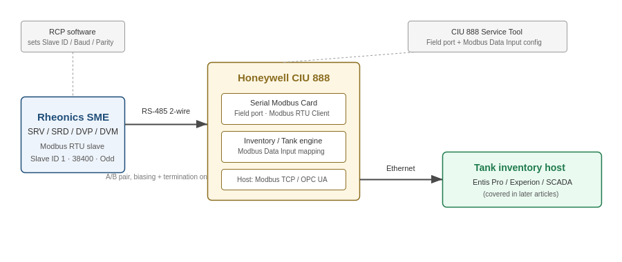
Figure 1. Rheonics SME to CIU 888 field port — scope of this article
2. Prerequisites
- Rheonics SRV, SRD, DVP or DVM with SME electronics, firmware V03.30 or higher (required for Modbus RTU support)
- Honeywell CIU 888 fitted with a Serial Modbus Card in a free option slot, running CIU 888 Service Tool R210 (or a compatible release)
- Rheonics Control Panel (RCP) software, to read/set the SME's Modbus address, baud rate and parity
- RS-485 2-wire cabling between the SME and the CIU 888 field port, with bus biasing and termination provided externally — the SME has no internal biasing or termination resistors
3. Confirm the SME's Modbus RTU settings in RCP
Before touching the CIU 888, confirm what the sensor is actually set to. Factory default on the SME is Slave Address 0 or 1, 38400 baud, Odd parity; the device also supports 9600/19200 baud and Odd/Even/None parity if the installation needs something else.
- Open RCP and connect to the SME (USB or RS-485).
- On the Communication settings tab, verify the Modbus Address, Baud Rate and Parity.
- If anything is changed, click Write Config and wait for confirmation before disconnecting.
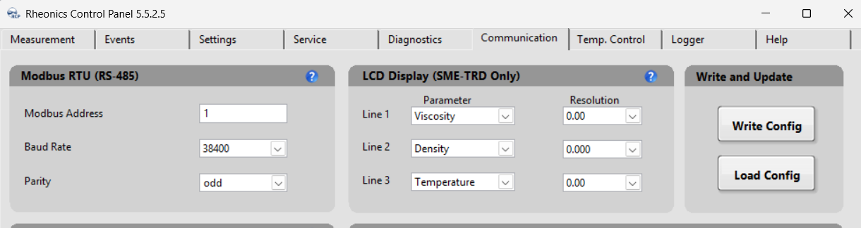
Note: Whatever Slave Address, Baud Rate and Parity you confirm here must match exactly what you configure on the CIU 888 RS Field Port in Section 5 — a mismatch on any one of the three is the most common reason a newly wired SME doesn't respond. |
4. Accessing the CIU 888
Configuration is normally done from a PC running CIU 888 Service Tool, connected to the CIU 888's Service port (front panel). The CIU 888 Web interface (browse to the CIU's IP address, default 192.168.1.1, and log in with the ciuadmin account) is used for diagnostics and for viewing communication status once the field port is live — see the System Administration Manual [1] for login and password management.
5. Configure the field port
In CIU 888 Service Tool:
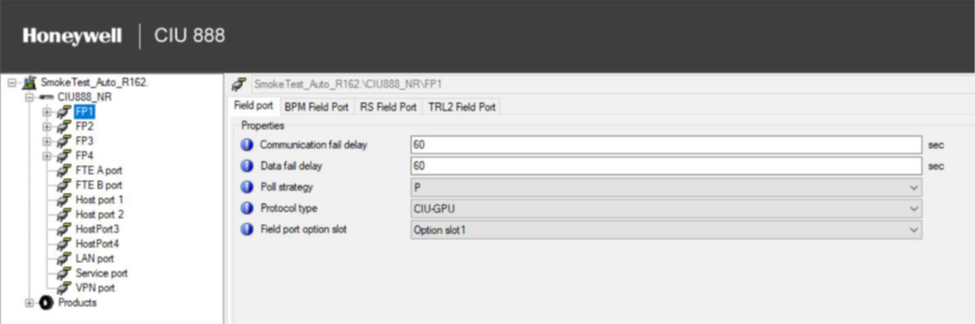
- Right-click the CIU 888 node and choose Add > Field port/Host port. Name the new field port.
- On the Field port tab, set Protocol Type to Modbus RTU, and assign Field port option slot to whichever slot holds the Serial Modbus Card.
- On the RS Field Port tab, set the properties below.
| Property | Value |
| Baud rate | Match the SME (default 38400) |
| Mode | RS 485 |
| Parity | Match the SME (default Odd) |
| Stop bits | 1 |
| Duplex mode | Full |
| Retries | 3 (default) |
| Time-out | See note below |
Time-out at lower baud rates: The CIU 888's default 250 ms Modbus time-out can be too short at 9600 or 19200 baud. Calculate it explicitly: Field port time-out = (1000 / baud rate) × bits per byte × maximum bytes retrieved in a single request, and configure the result instead of leaving the default. |
6. Build the SME Modbus device configuration file
The CIU 888 identifies a third-party Modbus device through an XML "device type" file that describes its register map. For the Rheonics SME, this file has to be authored following the CIU 888 Configuration Manual's device template. The key fields, populated for the SME's Density, Temperature and Viscosity registers, are:
Why Viscosity has no engineering unit: the CIU 888's device template only defines LEVEL, TEMPERATURE, DENSITY and PRESSURE as device unit types — there is no native VISCOSITY type. Density and Temperature are mapped as their proper typed units above; Viscosity is exposed as DeviceUnitType = ANY, meaning CIU 888 carries the raw value through without unit conversion. Any unit handling for viscosity has to happen downstream, in the tank/host application. |
7. Import the device file and map registers to a Tank
- Right-click the CIU 888 node and choose Import MODBUS device type file, then select the XML built above.
- On the relevant Tank node, right-click and choose Add > Modbus Data Input. Name it (e.g. M1).
- In the resulting grid, add one row per parameter:
| CIU Parameter | Device Type | Slave ID | Register Address | Engineering Unit |
| Observed Density | Rheonics SME | 1 | 300049 | kg/m³ |
| Product Temperature | Rheonics SME | 1 | 300057 | °C |
| (user-defined) Viscosity | Rheonics SME | 1 | 300041 | — (ANY) |
| Gauge Status | Rheonics SME | 1 | 300040 | — |
Device Modbus Start Address should be left at 0 for all rows — the Rheonics register numbers above (e.g. 300049) are already the absolute CIU-format addresses, since Absolute address = Device Modbus Start Address + Modbus Register Address.
8. Verify the configuration
- Send the configuration to the CIU 888 from Service Tool.
- In the CIU 888 Web interface Diagnostics window, check that the field port's communication status shows Normal/Connected.
- Cross-check the Density, Temperature and Viscosity values against a live reading from RCP or ModbusPoll before relying on them in the tank inventory calculation.
Related articles
Multi-drop architecture for multiple Rheonics sensors on one CIU 888 field port, getting Rheonics data into Entis tank inventory, and Rheonics data over Modbus TCP/OPC UA host ports are covered in separate articles.
References
[1] Honeywell, "Communication Interface Unit (CIU888)," product page. Available: https://process.honeywell.com/us/en/products/terminals/enraf-tank-gauging/communication-interface-unit-ciu888
[2] Rheonics Modbus RTU Operators Manual, MRTU-OP-2403 — https://cdn.rheonics.com/wp-content/uploads/2024/04/Rheonics-Modbus-RTU-Manual_MRTU-OP-2403.pdf
[3] Rheonics Support: Modbus Input Registers — https://support.rheonics.com/en/support/solutions/articles/81000297459-modbus-input-registers