
| What is the purpose of this article? To explain how a Rheonics density meter connects to a Honeywell Enraf CIU 888 over Modbus RTU, where the density value fits in the CIU 888 inventory calculation, and what must be confirmed before it is used as the density source. What products are involved? Rheonics SRD for liquid density, Rheonics DVP for gas density, and the Rheonics Sensor Electronics (SME) in its TRD, TR and DRM variants. |
TABLE OF CONTENTS
Honeywell's Enraf tank gauging system is a tank farm inventory measurement platform built in three layers:
- Field level gauges: servo and radar level gauges, and temperature elements.
- The CIU 888 communication interface, which scans field data and runs the inventory calculations.
- Host level software, such as Entis Pro or a DCS, which consumes that data.
Density is one of the inputs to those calculations. It is conventionally obtained from servo density dips or manual sampling. This article covers how a Rheonics density meter connects to this system as a continuous density source, and which sensor applies: the SRD for liquid density or the DVP for gas density.
Figure 1. Rheonics SRD Density and Viscosity Meter |
Figure 2. Rheonics DVP Density and Viscosity Sensor |
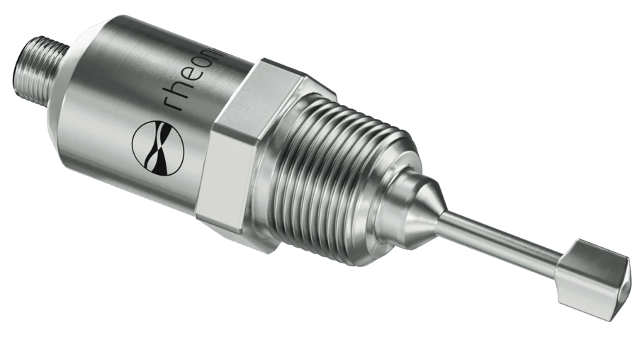
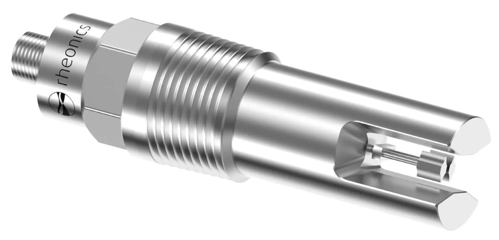
The Rheonics Sensor Electronics (SME) reads either sensor and carries the value onto the CIU 888. Three electronics variants are available:
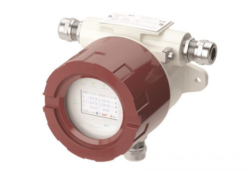 Figure 3. E1: SME‑TRD |
|
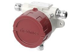 Figure 4. E2: SME‑TR |
|
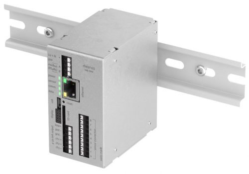 Figure 5. E3: SME‑DRM |
|
All three variants provide the same Modbus RTU interface to the CIU 888, so the choice between them depends on the installation, not on the integration.
The CIU 888 accepts Modbus field devices on one side and exposes standard protocols to the host on the other. This defines the integration paths available for Rheonics instruments.
The sections below cover each path, the inventory calculation the CIU 888 performs, and the serial and unit settings needed for commissioning.
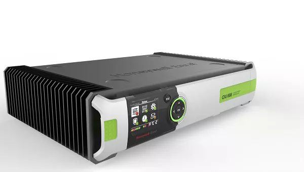
Figure 6. Honeywell Enraf CIU 888 [1]
1. Field side: Modbus RTU into the CIU 888
The CIU 888 Serial Modbus Input card works as a Modbus master over RS‑485 or RS‑232, with up to 32 Modbus field devices on one port in a multidrop configuration.
| A Rheonics sensor with Modbus RTU connects directly to a CIU 888 Serial Modbus Input port, with no protocol gateway. Whether that value can be used as observed density in the inventory calculation is covered in section 3. |
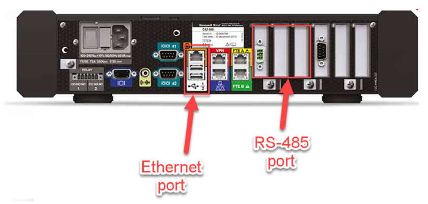
Figure 7. CIU 888 rear panel: Ethernet ports and option board slots for the Serial Modbus Input card [1]
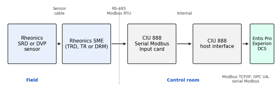
Figure 8. Signal path from the Rheonics sensor to the host system
2. Host side: Modbus TCP/IP, OPC UA and serial Modbus
Towards the host, the CIU 888 exposes Modbus TCP/IP, OPC UA and serial Modbus [1]. Once Rheonics data is scanned in on the field side, it is available to Entis Pro, Experion or other connected hosts through these interfaces. The corresponding tags still have to be configured on the host.
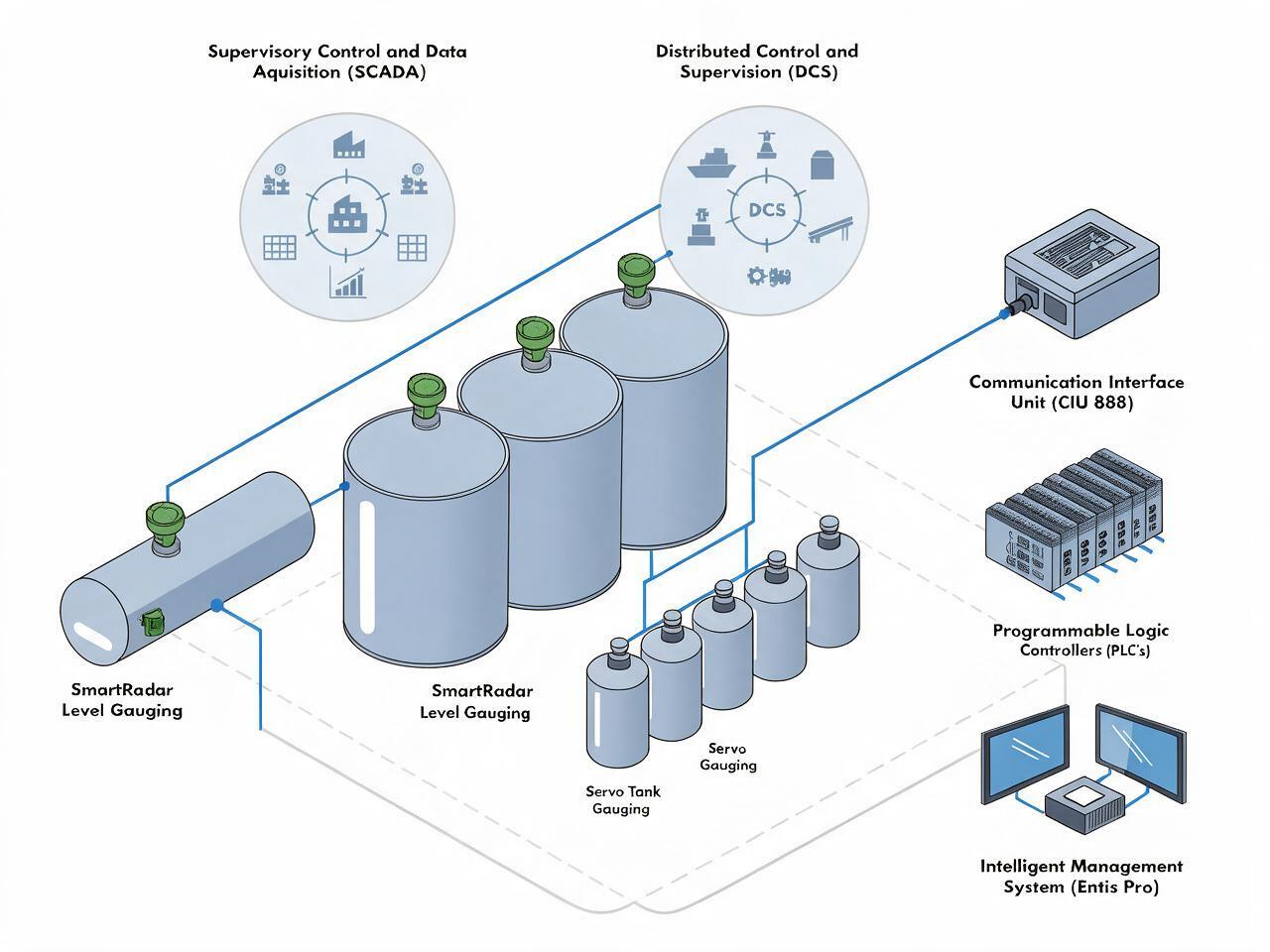
Figure 9. Field to host installation overview [1]
3. Calculation chain: where Rheonics density fits in
The CIU 888 performs inventory calculations per API MPMS Chapter 12.1 [2], with volume correction per ASTM D1250 / API MPMS Chapter 11.1 [3]. Observed density today typically comes from servo density dips or manual samples. A Rheonics density meter can provide a continuous value instead, subject to the integration consideration below.
Which Rheonics sensor to use. For liquid product tanks (crude, refined fuels, lubricating oils), the SRD provides the liquid density measurement. For gas or vapor phase applications, the DVP is the gas density sensor. Both connect to the CIU 888 the same way, through the SME on the Modbus field port.
What does ASTM D1250 do? API MPMS Chapter 11.1 / ASTM D1250 defines the volume correction for petroleum products. Observed density at observed temperature is first converted to a reference density: ρ15, ρ20 or API gravity at 60°F (Tables 53, 59 and 23 in the 1980 edition). That reference density is then combined with observed temperature to give CTL (Tables 54, 60 and 24). The 1980 edition is a set of printed tables. From D1250‑04 onward, the standard is an implementation procedure with defined coefficients, and the two editions give slightly different results. For this reason, the edition and the product group are configuration items on the CIU 888, and in custody transfer they are a Weights & Measures decision. The CIU 888 supports ASTM D1250‑80 and API MPMS Chapter 11.1 (2007, adjusted to ASTM D1250‑04 and IP 200), with product groups A (crude oil), B (refined products), C (special applications with a known thermal expansion coefficient) and D (lubricating oils) [1].
Why continuous density matters. CTL is driven mainly by product temperature, which the CIU 888 already scans continuously, so a continuous density feed changes CTL very little. Its value is in mass and product monitoring. Mass is calculated as GSV multiplied by reference density, so any error in density carries into the mass figure one for one. Continuous measurement also shows stratification, blending and off-specification receipts that periodic dips or sampling can miss.
| Integration consideration. Honeywell documentation lists Servo, HTG and HIMS as the supported sources of observed density for the CIU 888 inventory functions [1]. Before proposing an SRD or DVP as the density source for the embedded CIU calculation, confirm the actual integration path, for example whether the value can be mapped through a supported host or interface mechanism, or whether it requires emulation of a supported gauge. This is particularly important for custody transfer and Weights & Measures applications. The CIU 888 holds an OIML R85 certificate issued by NMi [4] and includes W&M sealing, and the density source is part of the approved configuration. Replacing it with another instrument requires confirmation that the configuration remains within the applicable approval and regulatory requirements. Where the SRD or DVP is used for operational inventory monitoring rather than sealed custody transfer calculations, state this explicitly and evaluate the integration on that basis. |
4. Serial compatibility check
Rheonics sensors ship with the following default serial configuration:
Table 1. Rheonics default Modbus RTU settings
| Parameter | Value |
|---|---|
| Slave ID | 1 |
| Baud rate | 38400 |
| Parity | Odd |
These defaults fall within the 1200 to 38400 baud range of the CIU 888 Serial Modbus Input card, so no baud rate change is needed on the field side for standard commissioning. On a multidrop port, give each sensor a unique slave ID.
5. Density unit conversion
The SRD and DVP report density in g/cc by default, and can be set to report kg/m³ or °API instead. The CIU 888 and the downstream inventory calculations typically expect kg/m³, °API or RD 60/60. If the sensor is left at its default unit, the conversion must be done at exactly one point in the chain, either at the sensor or at the CIU 888, never at both. Deciding where the conversion happens and confirming it during commissioning prevents the most common support ticket for this integration: a density value that reads correctly at the sensor but appears out of range at the host.
| Related articles See the SRD, DVP and SME (TRD, TR, DRM) product pages for full specifications. References [1] Honeywell, Enraf Tank Farm Gateway CIU 888 datasheet: PMC CIU888 Datasheet [2] API Manual of Petroleum Measurement Standards (MPMS), Chapter 12.1, Calculation of Static Petroleum Quantities [3] ASTM D1250 / API MPMS Chapter 11.1, Temperature and Pressure Volume Correction Factors for Generalized Crude Oils, Refined Products and Lubricating Oils [4] OIML certificate R85/2008‑A‑NL1‑22.01, CIU 888, NMi Certin B.V.: OIML R85 certificate |