Which Products are Involved?For SME-DRM (DIN rail mount) transmitter. Visit Rheonics product page: https://rheonics.com/products/
1. Can I connect using an ethernet cable directly from my computer or laptop?Rheonics ethernet-enabled sensor can connect with straight-through cables to ethernet ports that support Auto MDI-X after setting the correct IP address and Subnet mask. To correctly set the IP address and subnet mask on the SME (sensor electronics), check this support article https://support.rheonics.com/en/support/solutions/articles/81000397449-connecting-your-sme-using-ethernet
2. What to do if I want to connect to the sensor connected over LAN?This article is not for you, refer to the article for LAN connections. or check our RCP manual Rheonics Control Panel Section 4.1.2.
3. How do I connect to sensor SME electronics using an ethernet cable plugged directly into my computer?The connection between the SME and the PC directly with a single Ethernet cable is only possible if the PC ethernet device (NIC) supports Auto-MDI-X, In figure 1 it is shown how both the SME and a Laptop are connected and receive data through the RCP software.

4. What do I need to configure on the PC?The PC must be set as follow for the correct communication with the SME:
4.1. Open Control Panel
4.2. Select Network and internet 
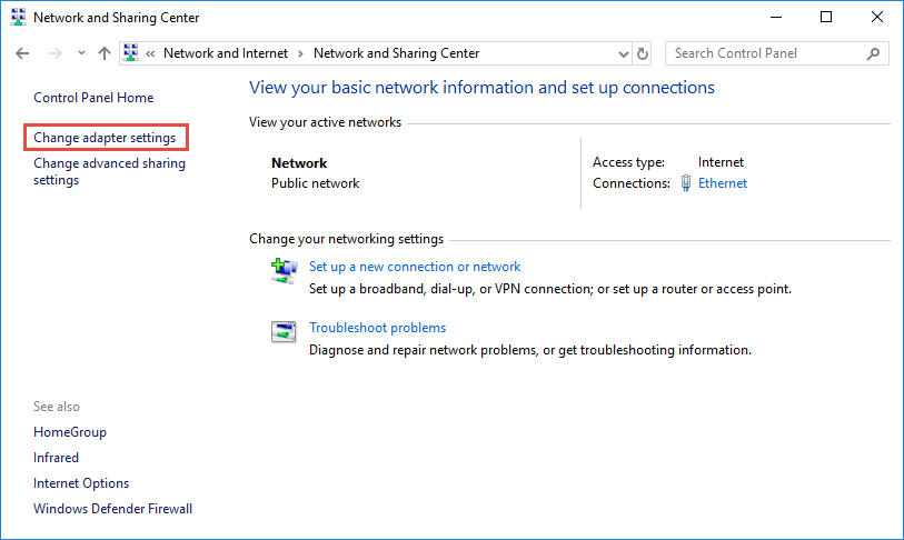
4.3. Click “Change adapter Settings”
4.4. Find your IP address, Right-click the ethernet ico, and select status from the context menu.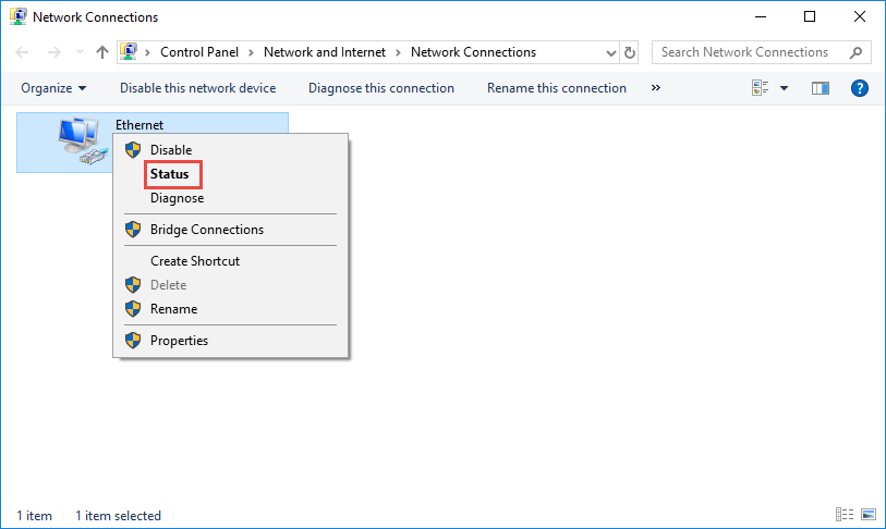
4.5. Look into the details of your own network
4.6. Set the IP address, Right-click Local Area connection, and select properties
4.7. Double click Internet Protocol Version 4 (TCP/IPv4).
 Figure 8. Internet protocol version 4 (TCP/IPv4)
4.8. Select “Use the Following IP address:” and type in the IP address, Subnet mask, and Default gateway. Click OK to apply the settings.

5. What do I need to configure on the SME electronics?
All configuration for the Network settings on the Rheonics sensor is done through the RCP software.
5.1. Open RCP and select the “Communication” Tab. The following steps should be done with USB communication in the “Setting tab”
 Figure 10. Communication tab in RCP software
5.2. Fill Ethernet parameters - Subnet Mask should be the same for both PC and SME.
Ethernet MAC | MAC Address is the physical address that identifies a device on the same local network. This value cannot be modified. |
DHCP | It is recommended to set this value as false if we are looking to integrate the sensor alongside other controllers. If the value is left to a true value, to identify the assigned IP address it is necessary the support from the IT department of your company. |
IP | IP address is a unique address that identifies a device on the internet or a local network. This address should not be duplicated on the same network to avoid conflict with the devices and is normally set by the integrator or IT department. |
Subnet | Subnet mask is a number that distinguishes the network address and the host address within an IP address. A subnet is a smaller network within a network that requires a subnet mask. This value depends on the IP class to be used normally, the most common one is Class C with 255.255.255.0 |
Gateway IP | A gateway is a network node that serves as an access point to another network. This value is commonly set to 0.0.0.0 if no access to other networks is required. Commonly used when we are going to use routers in our network. |
DNS | DNS stands for the Domain Name System, connecting domain names to IP addresses. Value can be set to 0.0.0.0 if not used. |
Terminal Port | The default port number used is 10001 for Telnet service. |
 Figure 11. Ethernet Parameters configured on the SME using RCP software
5.3. Click on the “Write config” button.

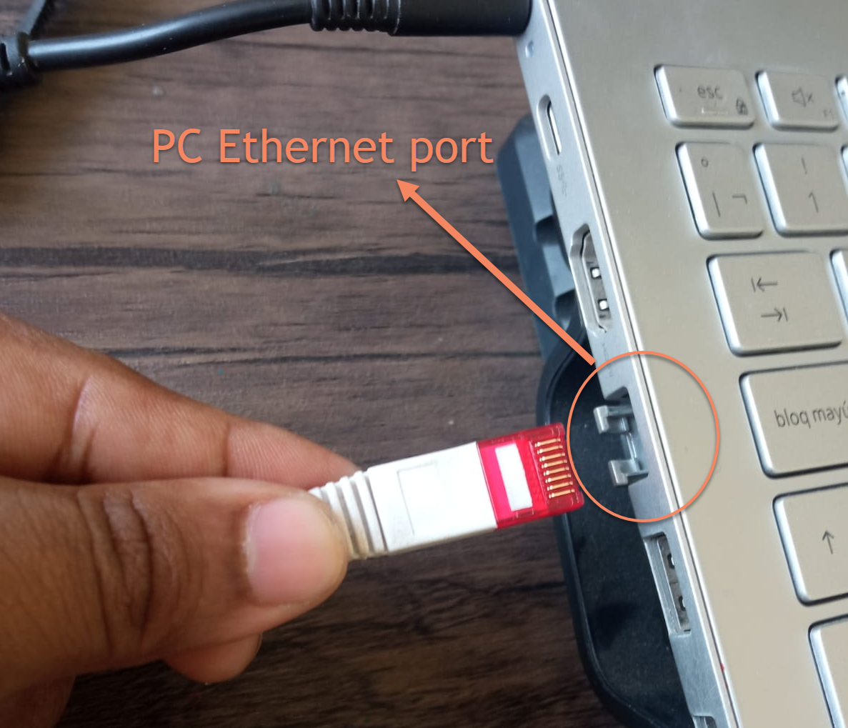
6. How do I connect the PC and SME?6.1. Next is to connect the same Ethernet cable to the PC and the SME. Be aware that most PC only has one ethernet port, so LAN connectivity won´t be possible over ethernet anymore (often wireless connections are available in PC which can be used during this time for internet connectivity if needed - RCP does not need internet connectivity for normal functioning). Find the Ethernet port on your computer and connect the ethernet cable.
6.2. Connect the Ethernet cable to the RJ45 ethernet port on the SME.
7. How do I use RCP software to connect to the Rheonics sensor over Ethernet?7.1. Once the Ethernet cable is connected on each end, it would be necessary to enable Ethernet communication. Set the IP address in RCP that you configured for the SME, go to the setting tab and select Ethernet in the radio button, fill in the same IP address you used in the “Communication” tab, and click the “Apply” button.
7.2. If everything is correct, status-led will turn green signaling communication between RCP on PC and the sensor SME.
7.3. After all the settings are complete, go to the “measurement tab” to verify that the data is being receive
8. What are MDI/MDIX and Auto MDI-X?
The MDI/MDIX are Ethernet interfaces (physical and electrical/optical) in a computer network that carry transmissions. Twisted pair cables should be connected so that the transmission pair on one end is connected to the receiving pair on the other. [1]
The MDI (Medium Dependent Interface) is an Ethernet port connection that connects to the NIC (Network Interface Card) or Integrated NIC port on a PC. Input and output signals on a NIC must be redirected to receiving signals on a hub or network switch. Thus, the latter devices use MDIX to switch transmission and receiving signals – X here stands for crossover, indicating that inputs and outputs are reversed.
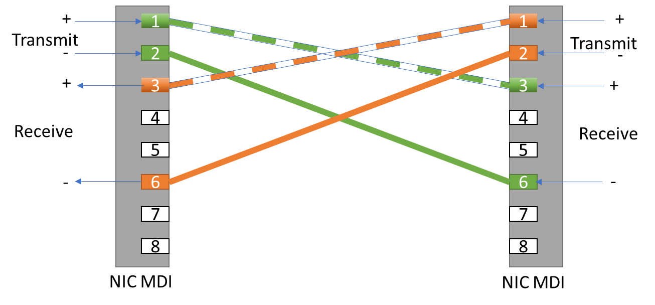
In routers, hubs, and network switches, MDIX (Medium Dependent Interface Crossover). A straight-through cable connects pins 1 and 2 (transmitting) of an MDI device to pins 1 and 2 (receiving) of an MDIX device, and vice versa for pins 3 and 6 (receiving) of an MDI device to pins 3 and 6 (transmitting) of an MDIX device. MDIX eliminates the need for crossover twisted pair cabling in this case.

The MDI interface is used by end stations such as PCs and workstations, while the MDIX interface is used by hubs and network switches. Often, routers have multiple MDIX ports and a single MDI port and to connect to other hubs or switches without a crossover Ethernet cable, some network hubs and switches have an MDI port.
The MDI and MDIX ports are generally connected via straight-through twisted pair cables.
Crossover twisted pair cables are used for MDI-to-MDI and MDIX-to-MDIX connections
Auto MDI-X is the solution to getting the wrong cable for any configuration, it will automatically detect cable type and configures the connection accordingly avoiding the issue of getting the wrong cable. Both types of cables can be used as long as the feature is enabled at either end of the link. [2]
Setting | MDI/MDIX Device Type | |
PC or other MDI device | Switch, hub, or other MDIX device | |
MDI | Crossover cable | Straight-through cable |
MDIX | Straight-through cable | Crossover cable |
Auto-MDI/MDIX | Either crossover or straight-through cable | |
9. How do I check my computer meets the requirements for the Ethernet cable direct connection?Ethernet card datasheet
Datasheet for the NIC should indicate if it is compatible with auto-MDI-x

- Verify that the NIC complies with 1000BASE-T standard
The 1000BASE-T standard was promoted by Daniel Joseph Dove[4]. Some Fast Ethernet devices might have Auto MDI-X function incorporated.
It requires that the interfaces be configured to auto-negotiate speed and duplex. This can be identified if we go to the Ethernet card properties>Advanced tab

10. FAQ/TroubleshootingProblem | Solution |
|---|---|
|
|
2. My PC support auto MDI-X, but still not getting data | 1. Verify that the SME has a static IP address and that DHCP is set as false. 2. Verify that you can ping the address with the console command ping AAA.BBB.CCC.DDD>IP address |
3. How do I check if my PC supports auto MDI-X? |
|
4. Which ethernet cable should I use crossover cable to straight-through cable? | 4. Any of the two configurations is compatible with Auto MDI-x |
5. Is there a software that I can use to verify if my ethernet card supports auto MDI-x | 5. Some manufacturers provide software that can provide the characteristics of the Ethernet card. Users can verify this by looking at the datasheet or checking if the system is Gigabit Ethernet. |
References1. https://community.fs.com/blog/mdi-vs-mdix-and-auto-mdimdix-basis.html [1]
2.http://www.hp.com/hpinfo/abouthp/iplicensing/automdix.html [2]
3. https://assets.alliedelec.com/v1590663186/Datasheets/fef893262b7bbaf1d59632d3c3c77bec.pdf [3]
4. https://www.ieee802.org/3/ab/public/feb98/ddmdix1.pdf [4]
5. https://support.rheonics.com/en/support/solutions/articles/81000397449-connecting-your-smet-using-ethernet
6. https://support.rheonics.com/en/support/solutions/articles/81000300292-introducing-ethernet-connections-on-smet
DISCLAIMER
Pictures, photos and images used are for illustration purposes and do not constitute any warranty or assertions on the suitability of use and should not be construed as an explicit or implicit recommendation or endorsement. All illustrations are given proper credit from our source of access and by their use here we do not specify or establish any copyright which belongs and stays unaffected with the existing copyright holder of that material.