
What products are involved?
SRD - Inline density and viscosity meter
What is the purpose of this article?
To give an overview of the SRD with Tri-Clamp connection, installation guidelines, instructions, special considerations and available accessories. Tri-Clamp connection varies in size but this article is valid for all of them.
1. IntroductionSRD is Rheonics sensor for inline density and viscosity measurements. Read more on SRD here.
At Rheonics, SRD with Tri-Clamp connection is typically on stock in different sizes. For some high sizes, less stock is available, so the lead-time for delivery can increase.
See all Tri-Clamp sizes available for Rheonics SRD inline density and viscosity meter.
See all CAD models for Rheonics SRD inline density and viscosity meter with Tri-Clamp connection.
A Tri-Clamp or TC fitting allows for an easy process installation in pipes and tanks. It is also widely used in the food industry, and at any place where frequent cleaning and disassembly are required. A TC connection is composed of 3 main parts: the ferrules, a gasket and a clamp. Find out how to select the correct gasket here. Pressure and temperature ratings vary for a Tri-Clamp connection, based on the type of clamp used.
Rheonics offers the SRD-HS-X3 as hygienic density and viscosity meter with 3-A and EHEDG certificates available.
 Figure 1: SRD-X3-1.5” Standard and Hygienic version dimensions.
| Specifications | |
|---|---|
| Sensor | Rheonics SRD |
| Order code | SRD-X3 |
| Connection type | Tri-Clamp |
| Sizes available | From DN25/32/40 - 1.5” - (OD 50.5)* up |
| Drawing and CAD file | |
*Smaller Tri-Clamp connections are available for flush sensor versions. Consider the SRD sensing element shown in Figure 2.
Check if your required Tri-Clamp norm and size meets the requirements for Rheonics SRD here.
Find CAD files for various TC sizes here.
2. General Installation Guidelines
SR-sensors can be placed at any point in a process and at any orientation but is helpful to consider some terms that are usually involved in the sensor measurements.
2.1 Submersion
The SRD has a sensing element shown inside the red section in Figure 2. This section of the sensor should always be fully submerged in the fluid since SRD measures what is in contact with its sensing element. Incomplete submersion can lead to innacurate or systematic errors in density and viscosity readings. This is a common issue with unfill pipes due to very low flow rate.
When there is a chance of incomplete pipe filling then consider installing the sensor in a flow cell or section which would ensure the section is full before fluid exits, this can be done by making the outlet higher than the inlet (Figure 3a and 3b). However here consideration should be given to create self-draining installs that minimizes the chances of sedimentation.

Figure 3: SRD sensing area.
Figure 3a shows an installation with the SRD in the IFC-15T-34N-SRD flow cell, inlet and outlet ports are 3/4” NPT threads.
Figure 3b shows an equivalent alternative with the FET-15T flow elbow tee from Rheonics which has a shorten 1.5” port for the probe, also available in 2” size.
Both solutions have the inlet below the outlet port to favor the complete immersion of the sensing element in the fluid before it exits the cell.
 Figure 2: Flow cell to ensure full immersion of sensor.

Figure 3b: Flow cell to ensure full immersion of sensor.
2.2 Stagnation/dead zone
Is not a good practice to have dead or stagnations zones around the sensing area (Figure 3). A stagnation or dead zone is where a fluid transfer is not good and older fluid may not be fully displaced by newer fluid. This leads to incorrect measurements due to part, or all, of the measurements being influenced by stationary fluid that is no longer representative of the actual process fluid.
Consider that some ferrules may cause dead zones in the gaps created with installation long standpipes. Rheonics recommends the use of short ferrules or its WFT-15T ferrule weldolet.
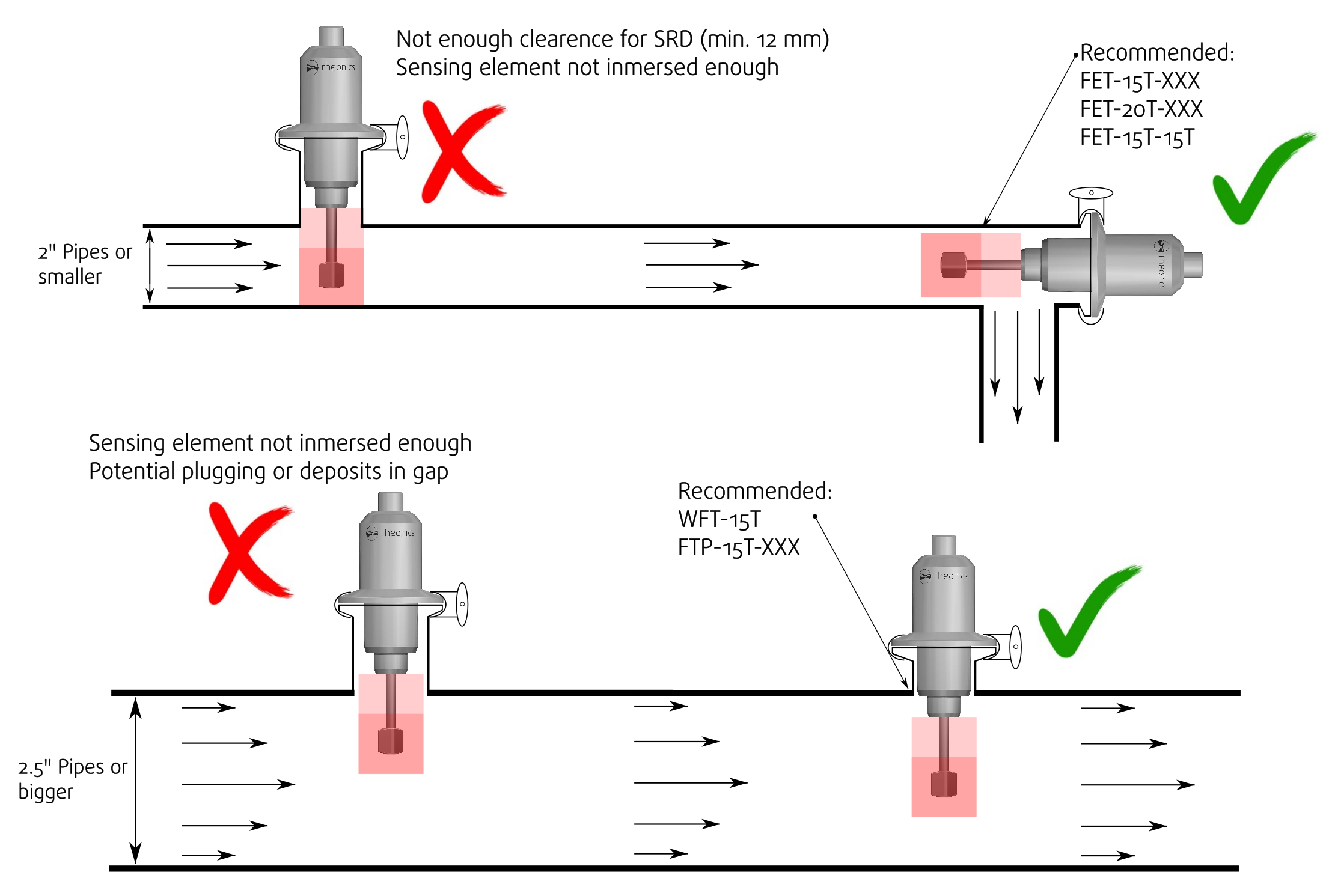
A clearance of at least 12mm is recommended between the SRD tip and the pipe wall or any other obstruction.
2.3 Recommended orientation
SRD has a sensing tip that is recommended to be aligned with the fluid flow direction to avoid creating recirculation zones around it. Read more on this topic, here.

Figure 4: SRD sensing tip.
2.4 Flow
For Newtonian fluids, the flow rate does not affect the measurements, so SRD should measure the same viscosity and density values in static and moving states of a fluid at the same temperature.
For non-Newtonian fluids (the vast majority of fluids) the flow rate does matter and viscosity readings may differ between static and moving conditions. Density readings, on the other hand, won't be affected as much as the viscosity reading, and for pure density applications, Newtonian and non-Newtonian fluids can be treated similarly.
For processes with non-constant flow rates, the recommendation is to install the SRD in a section in the pipeline with the most consistent flow rate to have steady reading values.
Flow rate is also relevant to ensure the full submersion of the SRD sensing element into the fluid. For a process with a low flow rate, pipes may not be full of fluid at all points, so SRD should then be placed in a section where the pipe is usually full of fluid (i.e. after a pump). Installing the sensor upwards can also solve the issue but should not be considered for fluids with solids or that can create deposits around the sensing element.
In all cases, the SRD’s sensing element should be submerged in the fluid. It’s best to avoid installations with long standpipes (i.e. using long weldolet or tee), since that may lead to not good fluid transfer resulting in measurements that do not reflect the true state of fluid or worse high noise measurements.
When installing in a standpipe, choose the appropriate insertion length of the sensor by selecting long insertion probes. This allows the sensing element to clear the stagnation zone and be in the fluid that is of interest for measurement, as in the next figure.
 Figure 5: Long insertion probes for long standpipes.
2.5 Fluid types
SRD has good performance with the following fluid types and scenarios:
- Static and moving Newtonian fluids
- Moving non-Newtonian fluids: Viscosity can vary at different flow rates, SRD needs to be fully submerged and without stagnation zones.
- Slurries: Typical use case for the SRD. Density in slurries vary with time, as slurry ages, and as it is mixed.
- Fluids with solids of micrometers scale: Solids of the size of rice corn shouldn’t affect measurements.
- Fluids with greater solids: Solids with a bigger size will most likely create spikes in the SRD readings when these hit the sensor. Depending on the percentage of solids in the fluid and after some data analysis, Rheonics may be able to apply some filters to handle these fluids better. However, it is hepful to avoid this kind of solids or install the sensor axially.
3. Process connection installation instructions
3.1 Connection steps
A Tri-Clamp connection requires two ferrules or flanges, a seal and a clamp, as in the next figure.

Figure 6: Tri-Clamp connection components.
The general steps for a Tri-Clamp connection are:
i. Have a welded ferrule in the pipe or tank.
ii. Place the gasket properly into the seat of the ferrule.
iii. Place the sensor Tri-Clamp connection on the gasket and verify it is correctly aligned.
iv. Loosen the clamp so it can fit around the ferrule.
v. Place the clamp, verify ferrules are within the clamp’s groove.
vi. Start tightening the clamp until a leak-proof connection is made.
Be careful not to over-tighten the clamp, this can damage the gasket and ferrules.
3.2 Specific Process Connection installation instructions
- In line: For inline installations consider the sensing area (Figure 3) and a minimum clearance of the sensor tip to the pipe inner wall (12 mm). A perpendicular Tri-Clamp installation of the SRD is not possible for most 1”, 1.5” or 2” pipes (for 2” it depends on the pipe norm). In those cases, the installation is recommended to be parallel or with a flow cell, check accessories FET-15T and IFC-15T-SRD. For bigger lines the sensor can be mounted perpendicular to the flow, Rheonics recommends the WFT-15T ferrule for such cases.
- In tank: Place the sensor at the bottom, wall or lid of the tank as long as the sensing element can be fully submerged in the fluid and dead zones are avoided. The WFT-15T ferrule is recommended for these installations. Usually, it is useful if the sensor is placed at a tank’s height that has always fluid. If there is a hygienic requirement, the SRD-TC can be ordered with a hygienic design as in Figure 1 (optional EHEDG and/or 3-A certification) and should be mounted with a hygienic adapter (e.g. flush welding flange like ISO 1127).
- Others: Larger pipelines or tanks often need a longer probe (i.e. jacketed tanks or pipes), in those scenarios, the client should use a long insertion probe (FPC sensors) - Order code: SRD-X5.
For special applications contact the Rheonics Team.
Important: Avoid using adapters to install the SRD in a Tri-Clamp port when the probe has a different process connection e.g. threaded. This is the case for NPT to Tri-Clamp adapters, as showm in Figure 8. Rheonics SRD should be ordered with the correct process connection to directly mount it inline without the need for additional adapters that can affect the correct immersion of the sensing element.

Figure 8: Recommendation to avoid NPT to Tri-Clamp adapters
3.3 Rheonics SRD Tri-Clamp Installation Examples
Next video shows installation examples and guidelines of the SRD with the Tri-Clamp connection.
4. Accessories available
4.1 Weldolet - WFT-15T
Weldolet for 1.5” Tri-Clamp sensor connection that ensures maximum submersion of the sensing element. Suitable for the SRD X3 1.5”. It can be used for process integration into Process lines, Mixing vessels, reactors, etc. Review its web page for more information.

Figure 9: WFT-15T ferrule
4.2 Flow cells
a. IFC-15T-SRD
Inline adapter for 1.5” Tri-Clamp sensor with 3/4” NPT inlet and outlet ports. This accessory is recommended for DN5 up to DN25 pipes, ensuring optimal flow over the sensing element and minimal stagnation zones. Review its web page for more information.

Figure 10: IFC-15T-SRD
b. FET-15T-XXX
Tri-Clamp elbow tee for 1.5” Tri-Clamp sensor with welding inlet and outlet ports of 1.5” size. Also available for other line sizes on request. Review its acccesory page here.

c. FET-15T-15T
Tri-Clamp elbow tee for 1.5” Tri-Clamp sensor (DN25/32/40) DIN11850 with same connection for inlet and outlet ports. Review its acccesory page here.
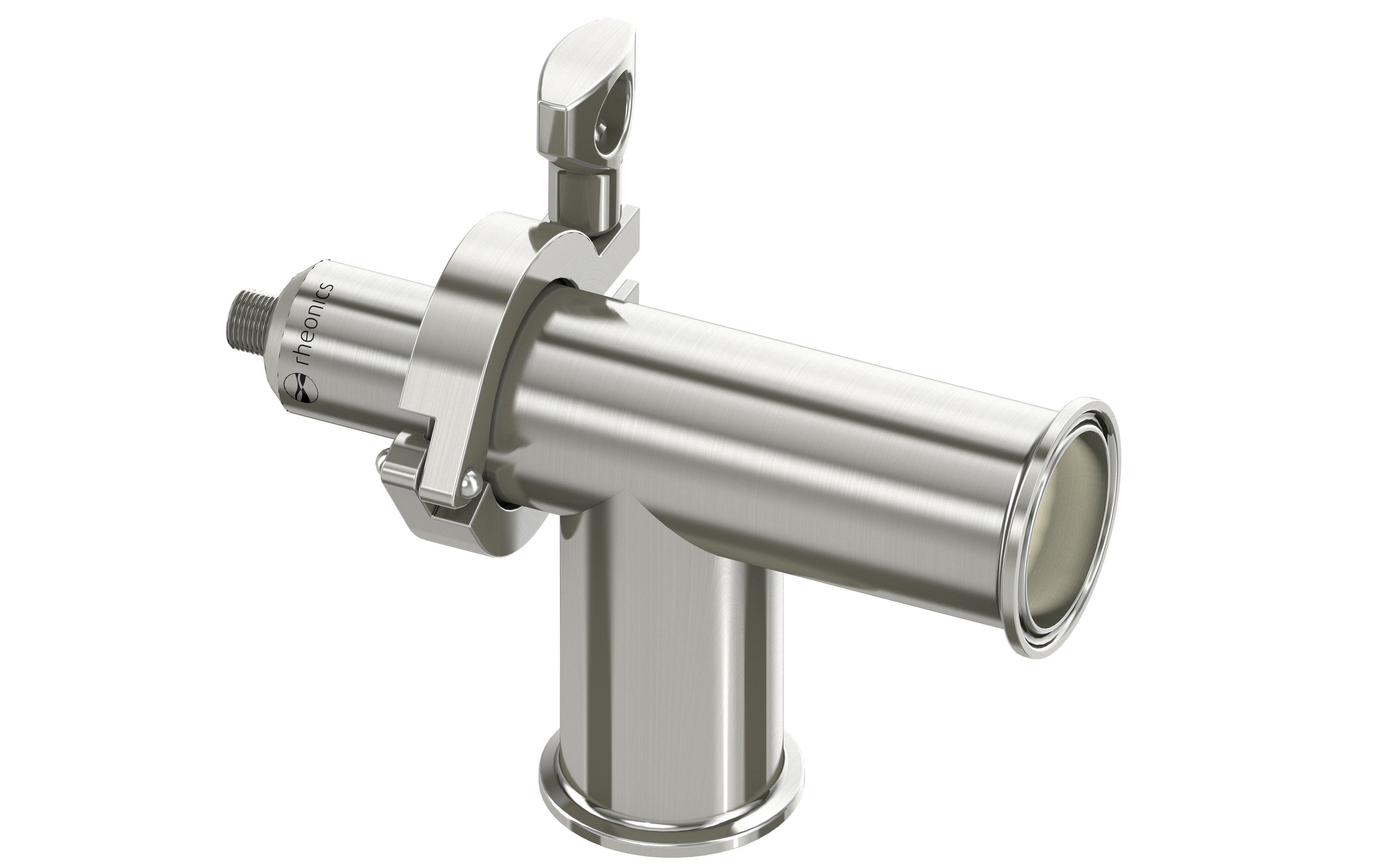
Figure 12: FET-15T-15T
d. FTP-15T-XXX
Tri-Clamp tee spool piece for perpendicular installation of the SRD with Tri-Clamp 1.5” process connection. Only available with welding inlet and outlet ports of 2", 3”, 4” or 6” size. Review its accessory page here.

Figure 13: FTP-15T-XXX
References[1]: https://rheonics.com/products/inline-viscometer-srd/