
What products are involved?Rheonics inline viscometers and density meters, with the transmitter electronics SME-TR, SME-TRD, and SME-DRM. What is the purpose of this article?To explain how to connect each wire of the sensor cable to the correct terminal on the SME electronics and how to safely disconnect the cable if needed. |
1. Overview
Rheonics inline viscometers and density meters are connected to the transmitter electronics (SME-TR, SME-TRD, SME-DRM) using a sensor cable.
The wiring depends on the sensor probe, and each SME is labeled with the wiring variant to use. The SME-DRM uses Variant A or B; the SME-TR and SME-TRD use Variants C and D, which follow the same wiring as A and B with the grounding on the terminal inside the housing [1], [2]. Section 2 shows how to find the variant and how to connect each wire. For the SME housings themselves, see Rheonics sensor electronics SME Drawings and 3D Models. For the wiring of your sensor, always check the operator manual that comes with your sensor.
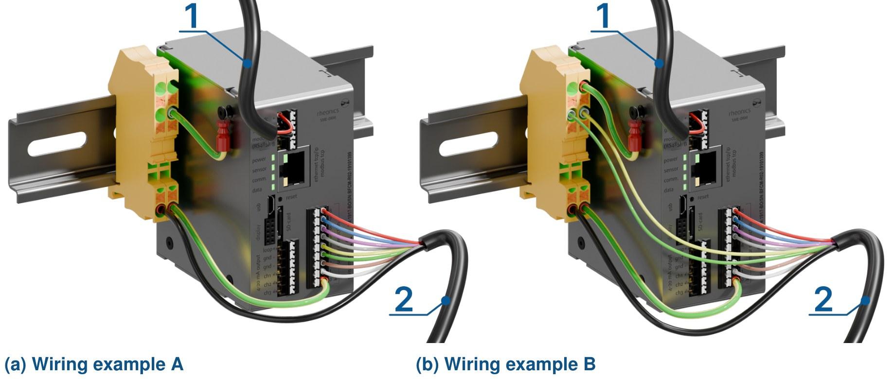
Figure 1. SME-DRM wiring examples, Variant A (left) and Variant B (right): 1 power (24V DC), 2 sensor cable
2. Wire Color and Terminal Assignment
The wiring depends on the sensor probe. The lower label on the side of the SME shows which wiring variant to use (Figure 2) [1], [2].
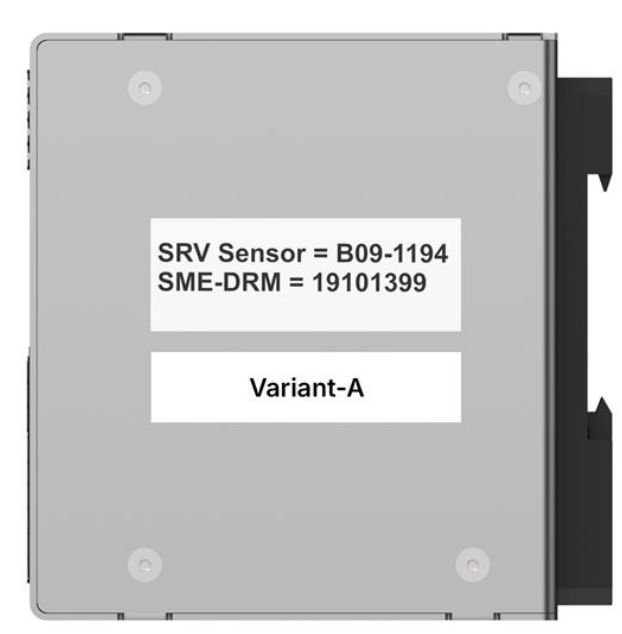
Figure 2. SME side labels: paired serial numbers (top) and wiring variant (bottom)
Connect each wire from the sensor cable to the terminal listed for your wiring variant in Table 1. In Variant B, wires 3 (green) and 4 (yellow) of the sensor cable go to ground instead of the SME, so SME terminals 3 and 4 stay empty. Terminal 0 goes to ground in both variants.
| Wire Color | Terminal #, Variant A | Terminal #, Variant B |
|---|---|---|
| Red | 8 | 8 |
| Blue | 7 | 7 |
| Pink (Rose) | 6 | 6 |
| Grey | 5 | 5 |
| Yellow | 4 | Ground |
| Green | 3 | Ground |
| Brown | 2 | 2 |
| White | 1 | 1 |
| Black (ground) | 0 | 0 |
Table 1. Sensor Cable Wire Color and Terminal Assignment, Variants A and B
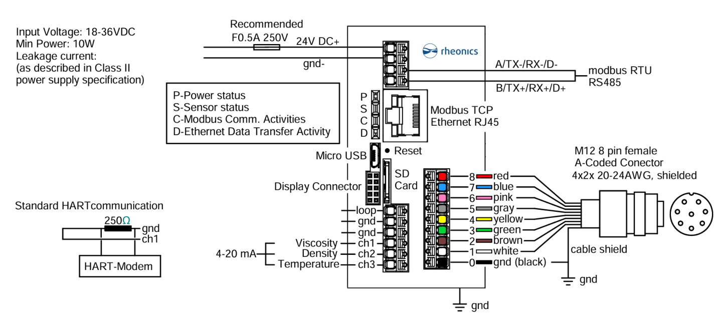
Figure 3. Sensor wiring, Variant A
The only difference between the two variants: in Variant B, the green and yellow wires (wires 3 and 4) run to ground, and SME terminals 3 and 4 stay empty (crossed out in Figure 4).
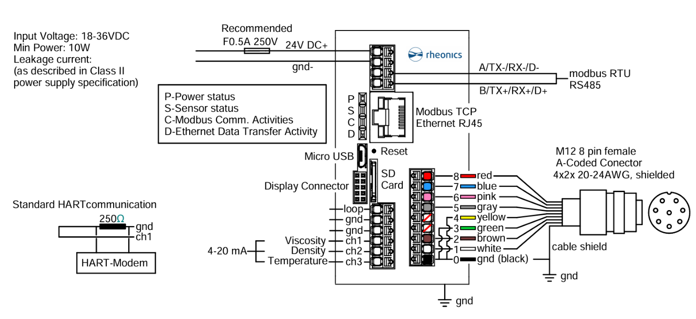
Figure 4. Sensor wiring, Variant B
The SME-TR and SME-TRD use Variants C and D: the same wiring as Variants A and B (use those columns of Table 1), with the grounding on the terminal inside the housing. For these variants and for grounding, check the operator manual that comes with your sensor. |
3. Cable and Crimp Preparation
The wire ends are delivered with crimped sleeves (8 mm pin length, 1 mm pin diameter) [3], [4], [5]. The cable can be shortened, if necessary, but sleeves must always be crimped on the stripped ends before connecting.
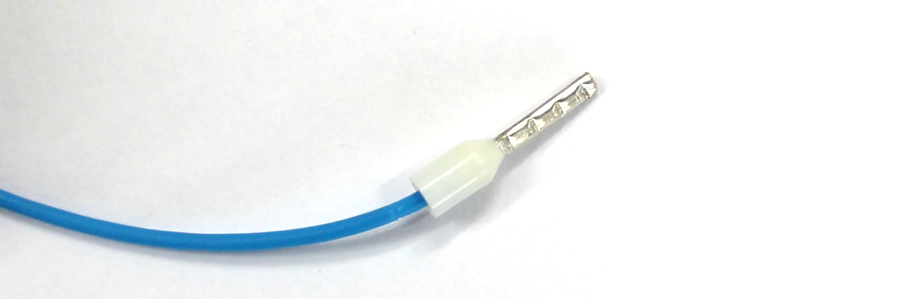
Figure 5. Crimped Sensor Cable
This procedure also applies to power cables, Modbus cables, and 4–20 mA signal cables. |
4. Connecting the Wires
- Disconnect all power before making electrical connections [1], [2].
- Use the column for your wiring variant in Table 1 to identify the correct terminal for each wire.
- Insert the crimped end of the wire into the terminal until it clicks firmly into place.
- Gently tug the wire to ensure a secure connection.
Do not pull with excessive force. This may damage the terminal block. |
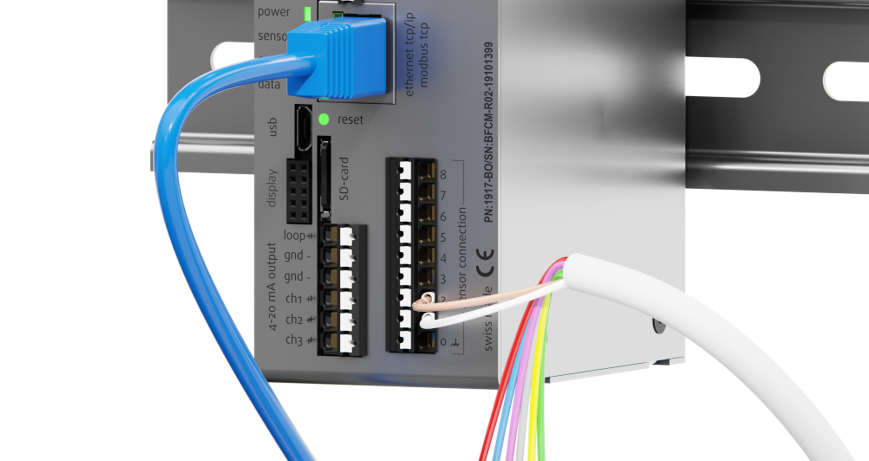
Figure 6. Connecting wire in Rheonics SME
5. Disconnecting the Wires
To safely remove a wire from the terminal block:
- Disconnect all power before removing wires.
- Press the white tab for that terminal using a small flat screwdriver (Figure 7).
- While pressing the tab, pull the wire straight out with your other hand.
- Ensure the wire is fully released before removing the screwdriver.
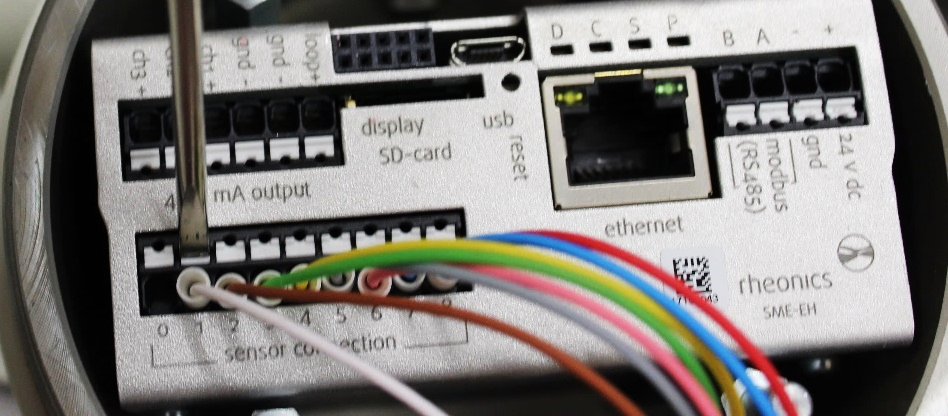
Figure 7. Disconnecting wire in Rheonics SME
6. References
- Rheonics GmbH, Rheonics SRV Inline Viscometer Manual, DocID SRV-G1-OP-2606, Jun. 2026.
- Rheonics GmbH, Rheonics SRD Inline Density and Viscosity Meter Manual, DocID SRD-G1-OP-2606, Jun. 2026.
- Rheonics, "Wire preparation for SME-DRM(Din Rail Mount)," Rheonics Support. [Online]. Available: https://support.rheonics.com/en/support/solutions/articles/81000408391. [Accessed: Sep. 23, 2026].
- Rheonics, "Wire preparation for SME-TR/TRD (Outdoor Mount)," Rheonics Support. [Online]. Available: https://support.rheonics.com/en/support/solutions/articles/81000410179. [Accessed: Sep. 23, 2026].
- Rheonics, "Wire preparation for Rheonics EX sensor," Rheonics Support. [Online]. Available: https://support.rheonics.com/en/support/solutions/articles/81000410683. [Accessed: Sep. 23, 2026].