ModbusPoll is a commercially available software from Witte GmbH.
1. Intro to Modbus RTU on Rheonics SME
All SME devices implement a MODBUS RTU-compliant RTU slave. The default configuration of the MODBUS RTU slave is 38400 and ODD parity. Connection is by RS485-2W where the interface is not electrically isolated. The SME device allows the configuration of the Modbus address using the RCP software. Please refer to the RCP manual for instructions.
Factory default settings of Modbus parameters:
Address=1
Baudrate=38400
Parity=odd
Databits:8
Slave Id: 1
Ensure that the electronic connections are accurately configured as per the diagram provided.
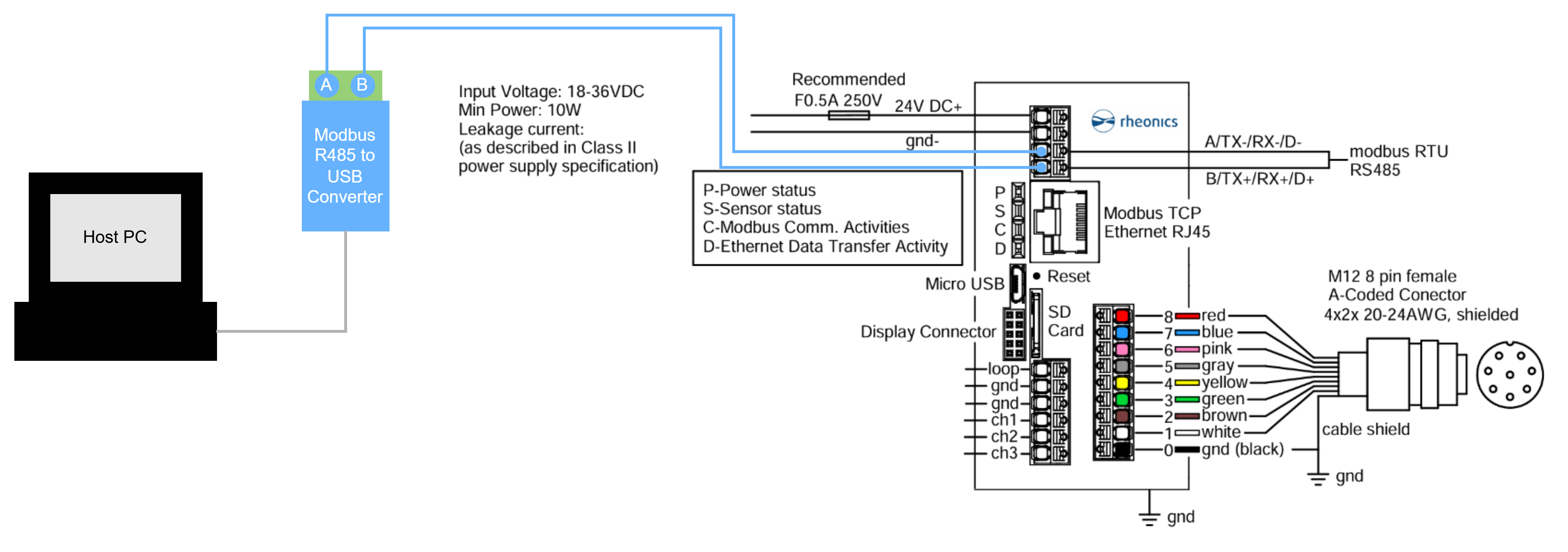
Figure 1. Wiring diagram to Host PC and Rheonics SME.
We suggest configuring your RS-485 network initially without terminating resistors. If communication issues arise, specifically those related to signal echoes or reflections, you may need to consider adding a 120-ohm terminating resistor to the RS-485 line. |
2. Intro to Modbuspoll tool RTU
2.1. Open the Modbuspoll tool. Below it is showcased how to set every parameter for the correct performance of the tool and to monitor the input registers of the SME..

Figure 2. Modbuspoll tool
2.2. Go to the communication Tab and select the connect option

Figure 3. Selection on the communication tab
2.3. Set all the parameters as shown below.

Figure 4. Connection configuration for Modbus RTU
2.4. Go to the “Setup” tab and select “Read/Write Definition”

Figure 5. Set the parameters to read the input registers in Modbus RTU.
2.5. The data from addresses 40 up to 49 is going to appear on the screen, this data corresponds to parameter 0. Check the following link for the mapped parameters

Figure 5. Input Registers data display
3. Correcting data types of registers and endianness
3.1. Right-click in the parameter to fix a value that is readable, a special menu is going to appear. Select “Format”

Figure 6. Menu editor for data format
3.2. Pay attention to the correct format of each parameter.

Figure 7. All options for data display
3.3. In the sample above, the address 40 corresponds to the following format (Float 32, Depending on the endianness of the host it might be necessary to swap high/low byte and/or the respective registers.)

Figure 8. Selecting the appropriate data type.
4. References