
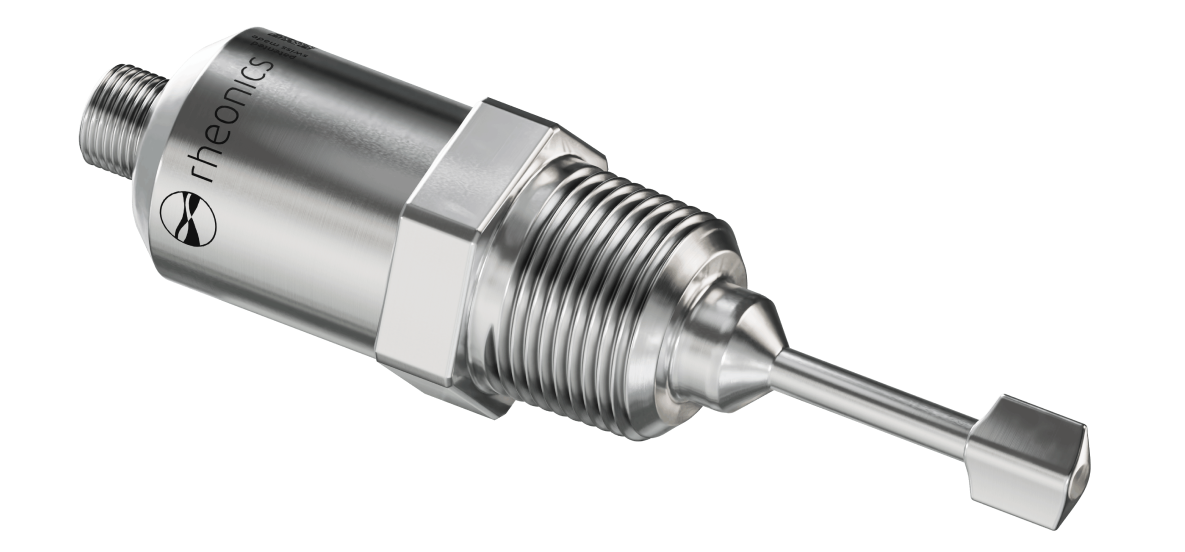
| What products are involved? SRD - Inline Density and Viscosity Meter |
| What is the purpose of this article? To give an overview of the SRD NPT 3/4” variant, installation guidelines, instructions, special considerations and available accessories. |
1. Introduction
SRD is Rheonics sensor for inline density and viscosity measurement. Read more on SRD here.
The NPT 3/4”-14 connection is Rheonics’ most commonly used design for SRD. In most cases, it is the most price-efficient option with the shortest lead time and the largest selection of accessories.
NPT threaded connections are very common in industrial applications. They are used in both low and high-pressure environments, up to 500 bar / 7500 psi. This type of connection allows for easy process integration using Rheonics accessories or a thread in a pipe or vessel.
This threaded connection requires the use of a Teflon band. This helps to ensure a sealed connection and avoids cold welds (the process connection adaptor may get stuck with the sensor, leading to severe damage).
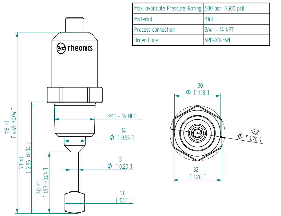
Figure 1: SRD NPT dimensions.
| Specifications | |
| Sensor | Rheonics SRD |
| Order code | SRD-X1-34N |
| Connection type | NPT |
| Thread size | 3/4" |
| Threads per inch (TPI) | 14 |
| Wrench for installation | 32mm (1-1/4") |
| CAD files | Download SRD 3/4" NPT Drawing Download SRD 3/4" NPT CAD files |
2. General Installation Guidelines
Before discussing the mechanical installation considerations of the SRD-3/4 NPT, it is important to mention some key points. The SRD has the same resonator across all its variants, with installation requirements related to the sensing area of the probe (shadowed red area, Figure 2), which are:
- This area should be free of deposits or obstructions
- This area should be completely filled with the fluid of interest
To achieve this installation requirement, the following considerations must be taken into account:
2.1 Submersion (proper insertion length)
As mentioned, the sensing area of the sensor should always be fully submerged in the fluid, since SRD measures what is in contact with its sensing element. This can be a problem when, in a process, the flow rate is low and the pipe isn’t usually completely filled, or when the sensor is installed too far out of the center of the pipe (usually for long standpipes on tees), where fluid gets stagnant and is not flowing properly, almost static. Notice also that a clearance of at least 5 mm is required between the sensor tip and a pipe wall or any other obstruction; this is usually considered for small-diameter pipelines.
Generally, to ensure proper immersion in perpendicular orientation with the fluid, the SRD-X1-34N is installed with the WOL-34NS or WOL-34NL. For parallel (elbow) installations, the flow cell IFC-34N-SRD is recommended.
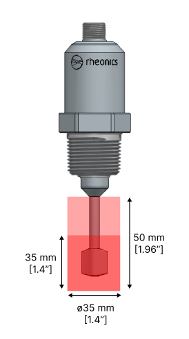
Figure 2: SRD sensing zone.
2.2 Stagnation / dead zone
For accurate measurements, stagnations and dead zones must be avoided. These are defined as any space inside the sensing area (red zone) where the fluid is stagnant or not flowing. Stagnation inside the sensing area can cause measurement issues for non-Newtonian fluids, promote the formation of deposits, and produce a slow response time due to the lack of fluid exchange. Avoiding stagnation in the sensing area is crucial for a stable, reliable, and fast measurement, especially for complex fluids.
2.3 Orientation dependency
SRD has a sensing tip that is recommended to be aligned with the fluid flow direction to avoid creating recirculation zones around it. This is only relevant for perpendicular installations. Read more on this topic here.

Figure 3: SRD sensing tip orientation.
2.4 Thermal balance
It’s important to consider that the short version of the SRD (e.g. SRD-X1-34N) is not suited to maintain accuracy on its density and viscosity readings over a large temperature mismatch between ambient and fluid. It is suitable for high-accuracy applications only when ambient conditions (at the probe back end) and fluid temperature are similar (within 15°C difference). A bigger temperature mismatch between the front (fluid) and back (body) of the resonator causes a frequency shift that influences readings. For applications with large differences between ambient and fluid temperature, the long insertion probe version of SRD is required, so both ends of the resonator are at the same temperature. Learn more here.
3. Additional considerations for the installation point
3.1 Flow rate
For Newtonian fluids, the flow rate that induces shear rate does not affect the viscosity in static or moving states of the fluid. However, for non-Newtonian fluids (the most common fluids used in industry), viscosity is shear-dependent and varies with the flow rate; therefore, viscosity readings will differ between static and different flowing conditions. For processes with non-constant flow rates, the recommendation is to install the SRD in a section of the pipeline with the most consistent flow rate to obtain a steady viscosity value.
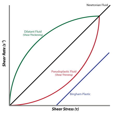
Figure 4: Viscosity behaviour by induced shear rate.
Flow rate is also relevant to ensure full submersion of the SRD sensing element into the fluid. The sensor should be placed in a section where the pipe is usually full of fluid (i.e., after a pump). However, if the pipe has a constant low flow rate, the pipe may not be full of fluid at all points.
Installing the sensor upwards can solve the issue, as shown in Figure 5. Still, it should not be considered for fluids with solids or characteristics that can create deposits around the sensing element. An angled or side-of-the-pipe installation could also help.
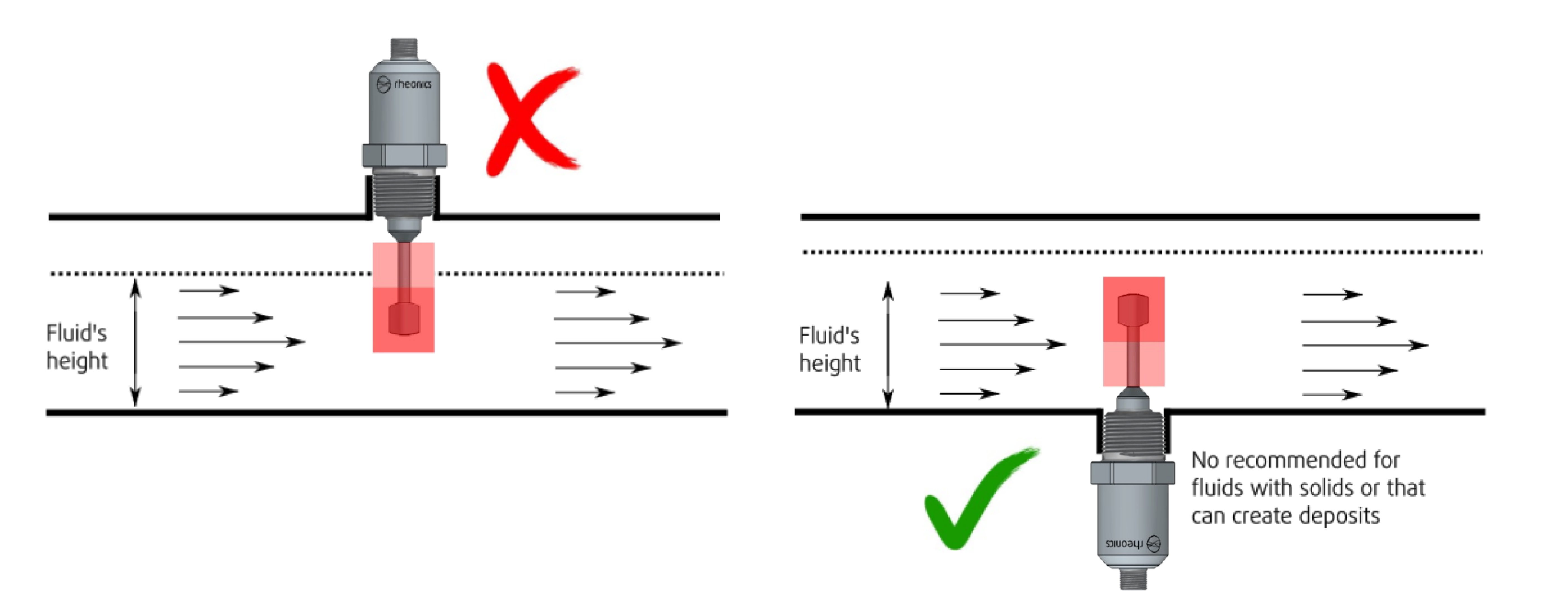
Figure 5: Pipe not fully filled with fluid.
In all cases, the SRD’s sensing element should be submerged in the fluid. It’s best to avoid installations with long standpipes (i.e., using a long weldolet or tee), since that may lead to poor fluid transfer, resulting in measurements that do not reflect the true state of the fluid or, worse, high-noise measurements.
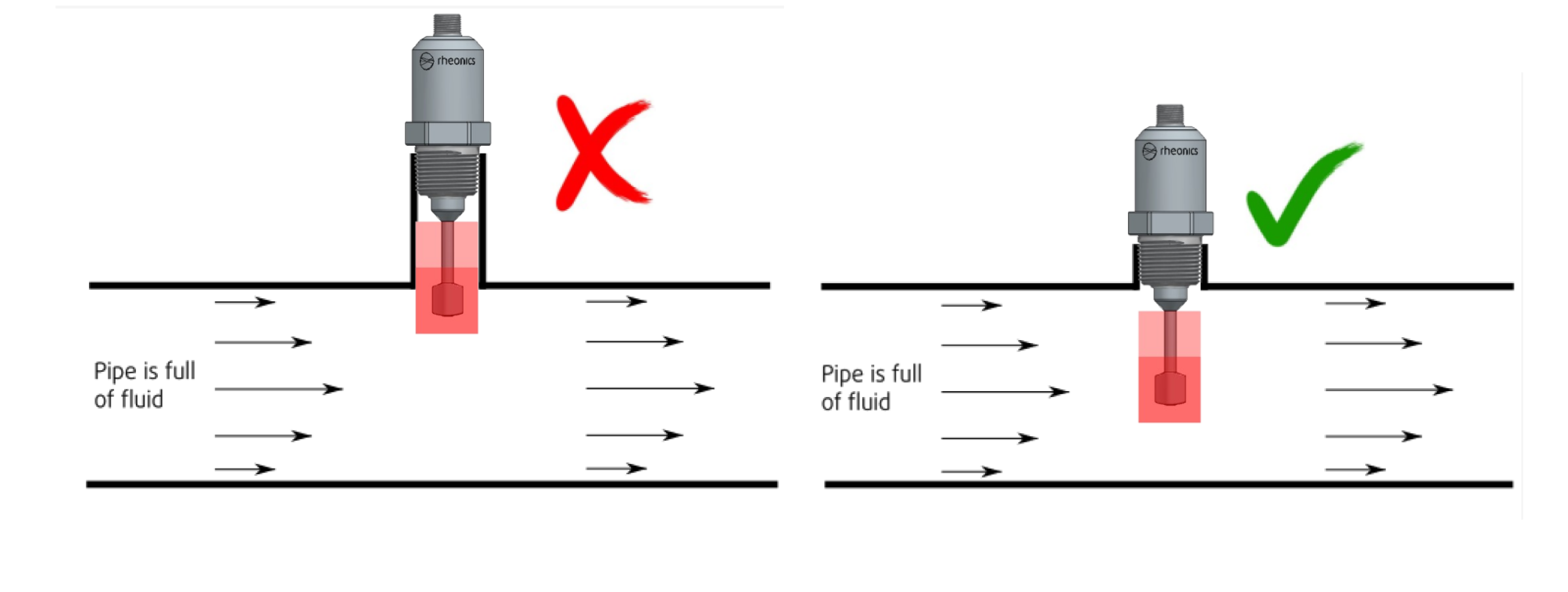
Figure 6: Flow conditions in installation.
3.2 Fluid type
The SRD, in general, works well with almost all fluids as long as the installation is correct. Some common fluid types and scenarios are:
- Static Newtonian fluids.
- Moving Newtonian fluids, regardless of flow rate changes (for non-Newtonian fluids, viscosity changes with flow rate, but SRD ensures reproducibility at constant flow rates).
- Avoid bubbly fluids or a high percentage of bubbles or air in the fluid. Bubbles can add too much noise to the SRD readings. Contact Rheonics Support to evaluate whether filters can be applied to minimize the effect.
- SRD works for flow velocities up to 12 m/s, depending on the probe orientation. Read more here.
Important installation considerations for these and other specific fluid types are given in this article.
4. Installation common issues
As explained above, accurate, repeatable, and reproducible readings from the SRD depend on maintaining proper installation of the sensing element. Below are examples of scenarios where these considerations are not met, leading to potential issues in the readings:
4.1 Potential issue – NPT Tee connection
Potential issue: A common mistake with installations of the SRD-X1-34N is using an off-the-shelf NPT Tee (Figure 7). An installation with the SRD, mounted vertically or horizontally in such a Tee port, can be prone to stagnant and dead zones.
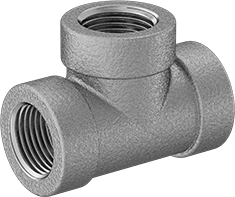
Figure 7: Standard NPT Tee [6]
Recommendation: In these cases, the Rheonics IFC-34N-SRD is recommended to ensure the flow surrounds the sensing element properly and stagnant zones are removed, as in Figure 8.
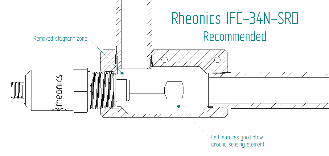
Figure 8: Correct installation in Rheonics NPT flow cell.
4.2 Potential issue – NPT connection adapter
Potential issue: At times, users may want to adapt the 3/4” NPT connection of the SRD-X1 to a different flange, like Tri-Clamp, using an adapter similar to the one shown in Figure 9. Mounting the SRD probe in these adapters can lead to both incomplete immersion and stagnation zones prone to fouling or deposits at the base of the sensing element, which will affect the measurements (see Figure 10). This scenario may not affect applications for low-viscosity fluids like ink but could be a significant problem for high-viscosity fluids like dough, adhesives, glue, and others.
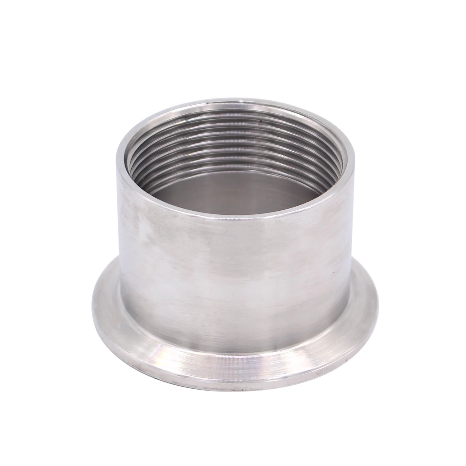
Figure 9: Standard NPT to Tri-Clamp adapter [7]
Recommendation: The client should order the SRD with the required process connection to mount the probe directly inline, without the need for additional adapters (Figure 10, installation to the right). If Tri-Clamp is required, see the SRD-X3. If custom flanges are required, see the SRD-X2.

Figure 10: Installation recommendation with NPT adapters.
5. Process connection installation instructions
5.1 Connection steps
i. Wrap a sealing compound (e.g. Teflon tape) around the sensor NPT thread 1.5 to 3 times in a clockwise direction, to ensure a leak-free seal.
ii. Place the sensor in the female threaded accessory.
iii. Turn the sensor NPT thread by hand until hand-tightened.
iv. Use a wrench (32mm / 1-1/4") to give the sensor 1 to 3 more full turns.
In total, according to ASME Standards, at least 3.5 and at most 6 full turns need to be ensured for a correct NPT installation. The sensor should not be completely tightened.
5.2 Specific process connection installation instructions
- In line: Ensure the sensing element is exposed to fluid, and avoid stagnation and dead zones. Consider placing the sensor upwards or parallel to the fluid for small flow rates that can’t fully surround the sensing element.
- In tank: Place the sensor at the bottom, wall, or lid of the tank, as long as the sensing element can be fully submerged in the fluid and dead zones are avoided. Usually it is useful to place the sensor at a tank height that always has fluid. The Rheonics TMA-34N accessory is a tank mount adapter used for NPT SR-sensors and should be considered for tank installations; see section 6.3 below.
- Others – thread flange: The SRD NPT sensor can be mounted on a thread flange of the same size (3/4"-14). The flange needs to have an inner diameter larger than 26mm on the process side, the material should be either 304 or 316L, and the height can’t exceed 25mm. If the flange has a greater height, an FPC-type (long insertion) sensor is needed. As with any installation, stagnation zones around the sensing element should be avoided; for thread flanges, the height of the standpipe of the connection is relevant, as shown in Figure 11.
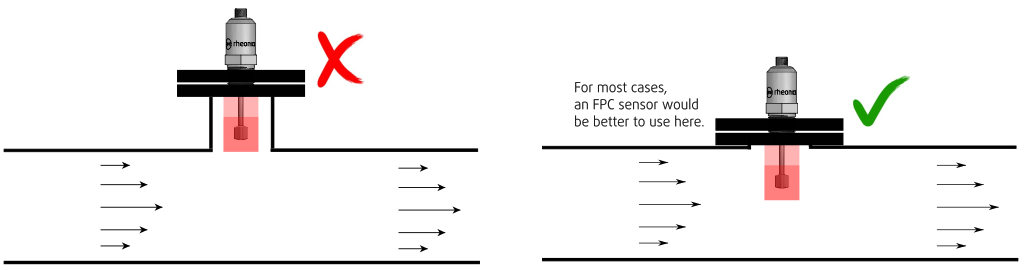
Figure 11: Threaded flange.
6. Accessories available
6.1 Weldolets
a. WOL-34NS
Weldolet for 2” pipes that ensures maximum exposure of the sensing element to the fluid. Also suitable for SRV NPT 3/4”-14. See the WOL-34NS page for more information.

Figure 12: WOL-34NS [3]
b. WOL-34NL
Weldolet for 2.5” and larger pipes, also suitable for tank installations, that ensures maximum exposure of the sensing element to the fluid. Also suitable for SRV NPT 3/4”-14. See the WOL-34NL page for more information.

Figure 13: WOL-34NL [4]
6.2 Flow cells
a. IFC-34N-SRD
Suitable only for SRD NPT 3/4”-14, and recommended for inline installation with nominal diameters of DN5 to DN25. Connecting threads for this accessory are NPT 3/4”-14. (A different variant is available for the SRV NPT.)
For diameters larger than DN25 (1”), we recommend using a bypass. The flow cell can then be connected via flexible hoses or fixed piping. Installing the sensor in a bypass is a common solution for process lines that require intensive cleaning by pigging.
Read more on its accessories page.
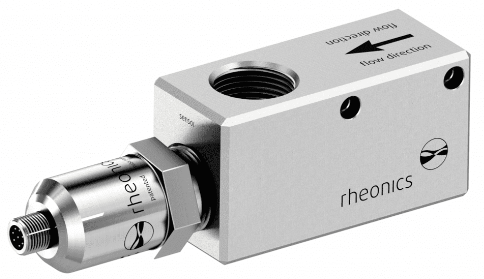
Figure 14: IFC-34N-SRD.
6.3 Tank mount adapter – TMA-34N
Suitable for SRV and SRD only in their NPT 3/4"-14 variant, this accessory is recommended for open vessels or tanks with a lid. It is composed of a small cell, in which the sensor is installed, and a 3/4" pipe fixed at the top with a variable length so the sensor can reach as far as needed.
Read more on the accessories page or in its support article here.
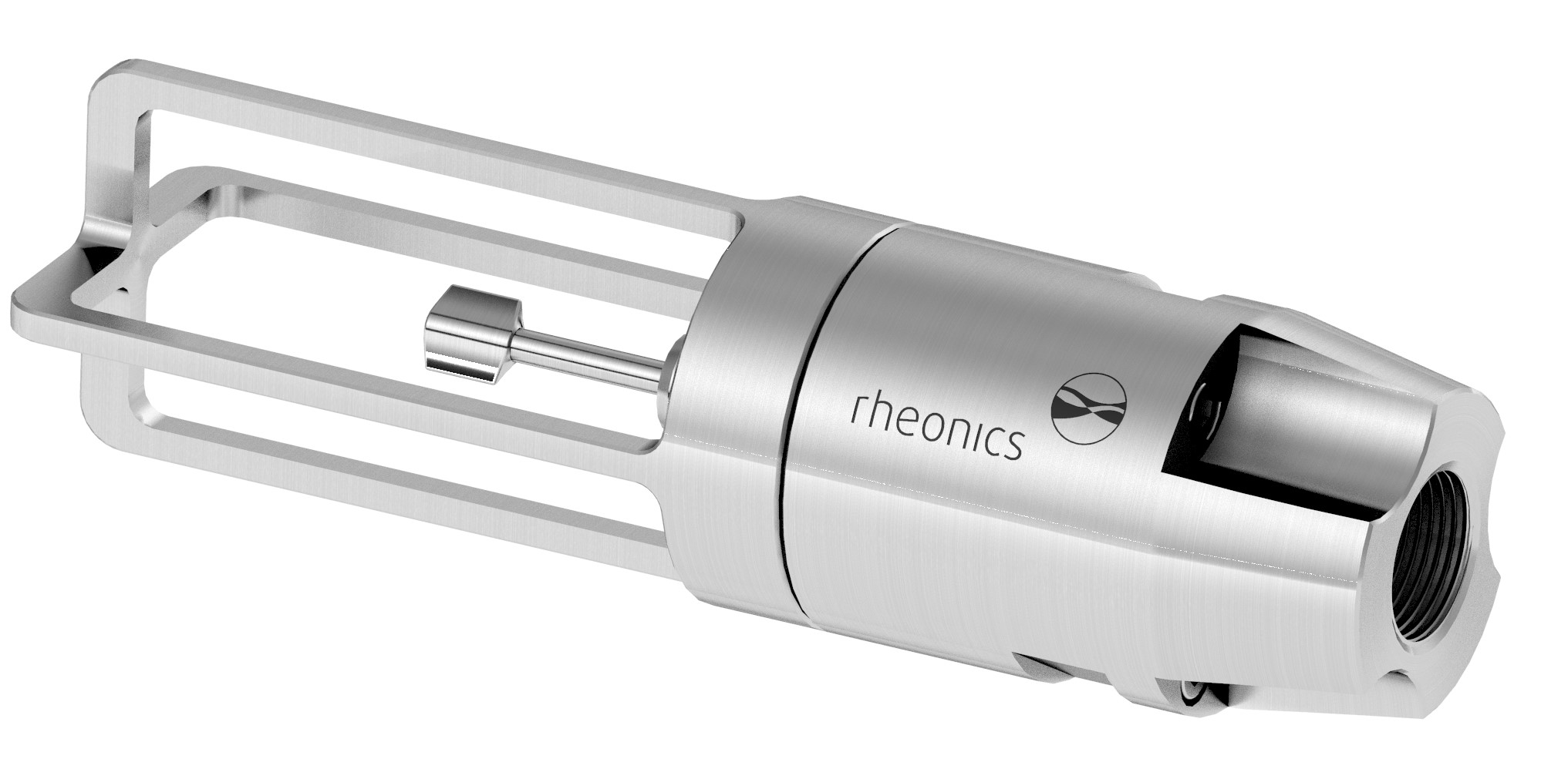
Figure 15: TMA-34N with SRD.
References
[1]: https://es.rheonics.com/products/inline-density-meter-srd/
[2]: https://rheonics.com/product-accessories/
[3]: https://rheonics.com/product-accessories/wol-34ns/
[4]: https://rheonics.com/product-accessories/wol-34nl-accessory-page/
[5]: https://www.asme.org/codes-standards/find-codes-standards/b1-20-1-pipe-threads-general-purpose-inch
[6]: https://www.mcmaster.com/products/tees/low-pressure-stainless-steel-threaded-pipe-fittings-9/
[7]: https://www.dernord.com/products/sanitary-female-threaded-pipe-fitting-to-tri-clamp?variant=27282774949952