What products are involved?
This article is based on using the SenseCAP M2 LoRaWAN gateway.
What is the purpose of this article?
This article walks through the process of configuring the SenseCAP M2 gateway to transmit data wirelessly and access it via The Things Network (TTN), which is a LoRaWAN ecosystem that includes The Things Stack (TTS), for remote monitoring.
TABLE OF CONTENTS
- 1. Overview
- 2. Gateway Configuration on The Things Stack (TTS)
- 3. SenseCAP M2 Multi-Platform Gateway Web Server Configuration
- 4. References
1. Overview
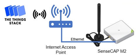
LoRaWAN is a long-range, low-power communication protocol designed for transmitting sensor data over wide areas. The SenseCAP M2 is a LoRaWAN gateway that provides long-range connectivity with other LoRaWAN devices, enabling them to send and receive data. Through the gateway, the data is sent to a LoRaWAN network server, where it can then be processed and visualized remotely. In this article, the SenseCAP M2 LoRaWAN gateway, which connects to the Internet (via Ethernet or Wi-Fi), allows sending data to a LoRaWAN network server such as The Things Stack (TTS). This allows the remote visualization of devices connected to the gateway.
To learn more about LoRaWAN refer to LoRaWAN Fundamentals Using the SenseCAP M2 gateway, Rheonics sensors can transmit sensor values wirelessly and be monitored in real time from anywhere through The Things Stack server.
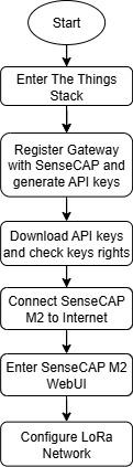
The following diagram illustrates the connection process between the SenseCAP M2 and The Things Stack.
2. Gateway Configuration on The Things Stack (TTS)
The SenseCAP M2 gateway needs to be added to The Things Stack to retrieve data from the Rheonics Sensor Module Electronics (SME).
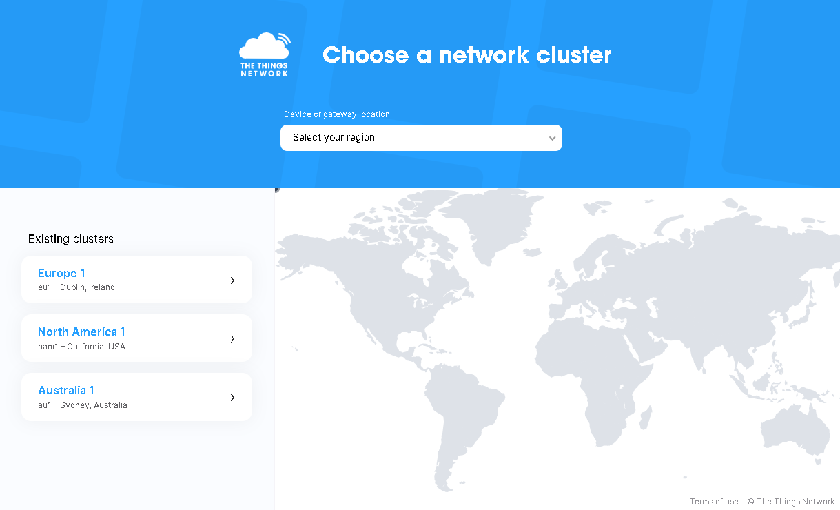
1. Enter The Things Network Console and select the cluster that matches the frequency plan of the SenseCAP M2 gateway. In this case, the Europe (eu1) cluster is chosen because the SenseCAP M2 EU868 version is being used.
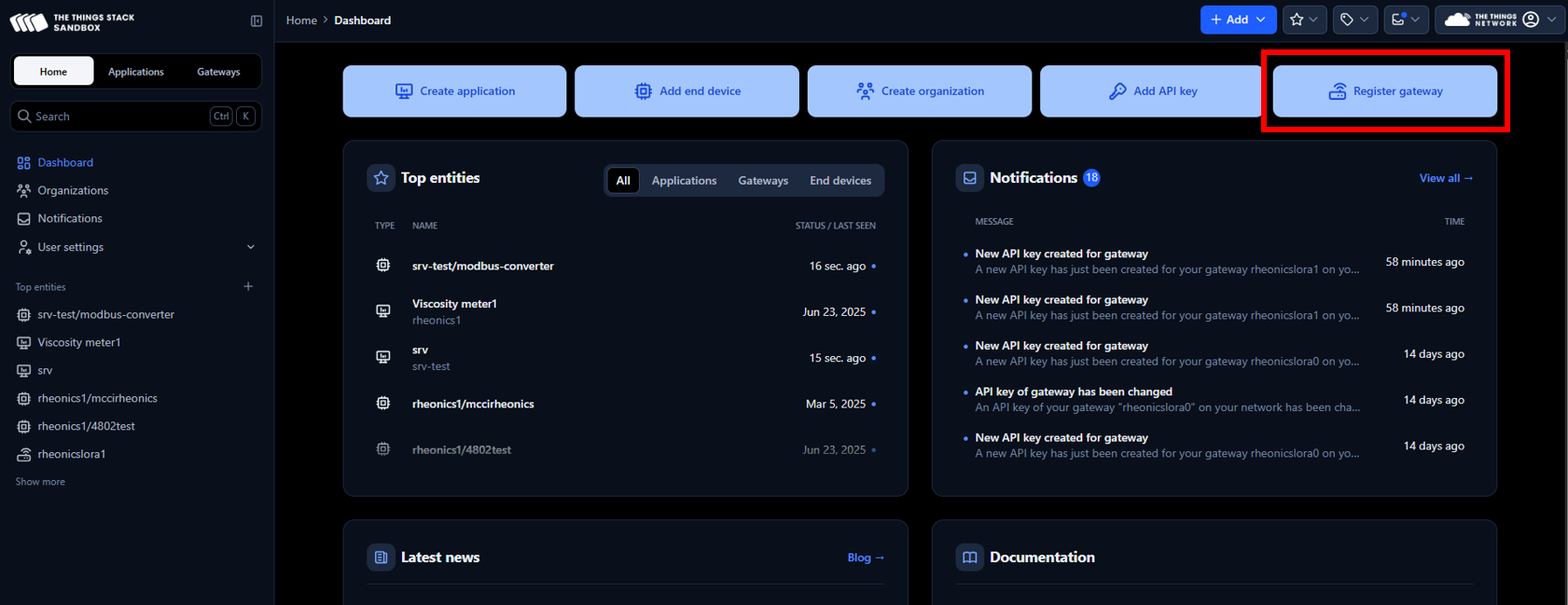
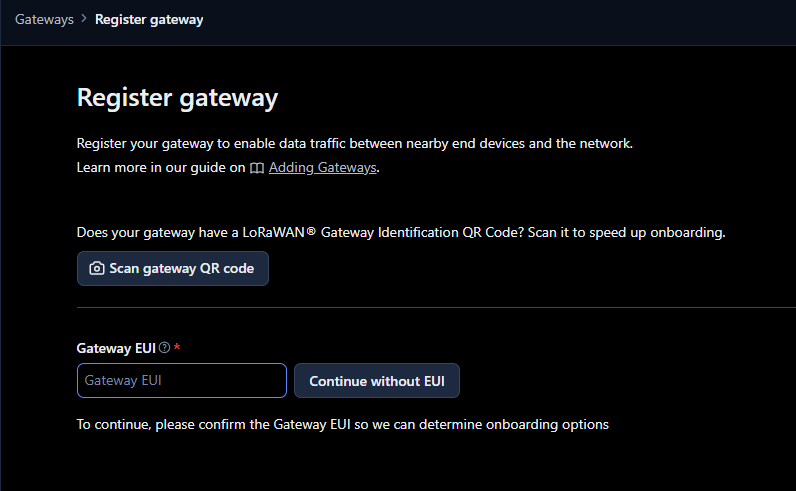
2. After logging in, click on Register Gateway
3. Enter the Gateway EUI found in the SenseCAP M2 device label.
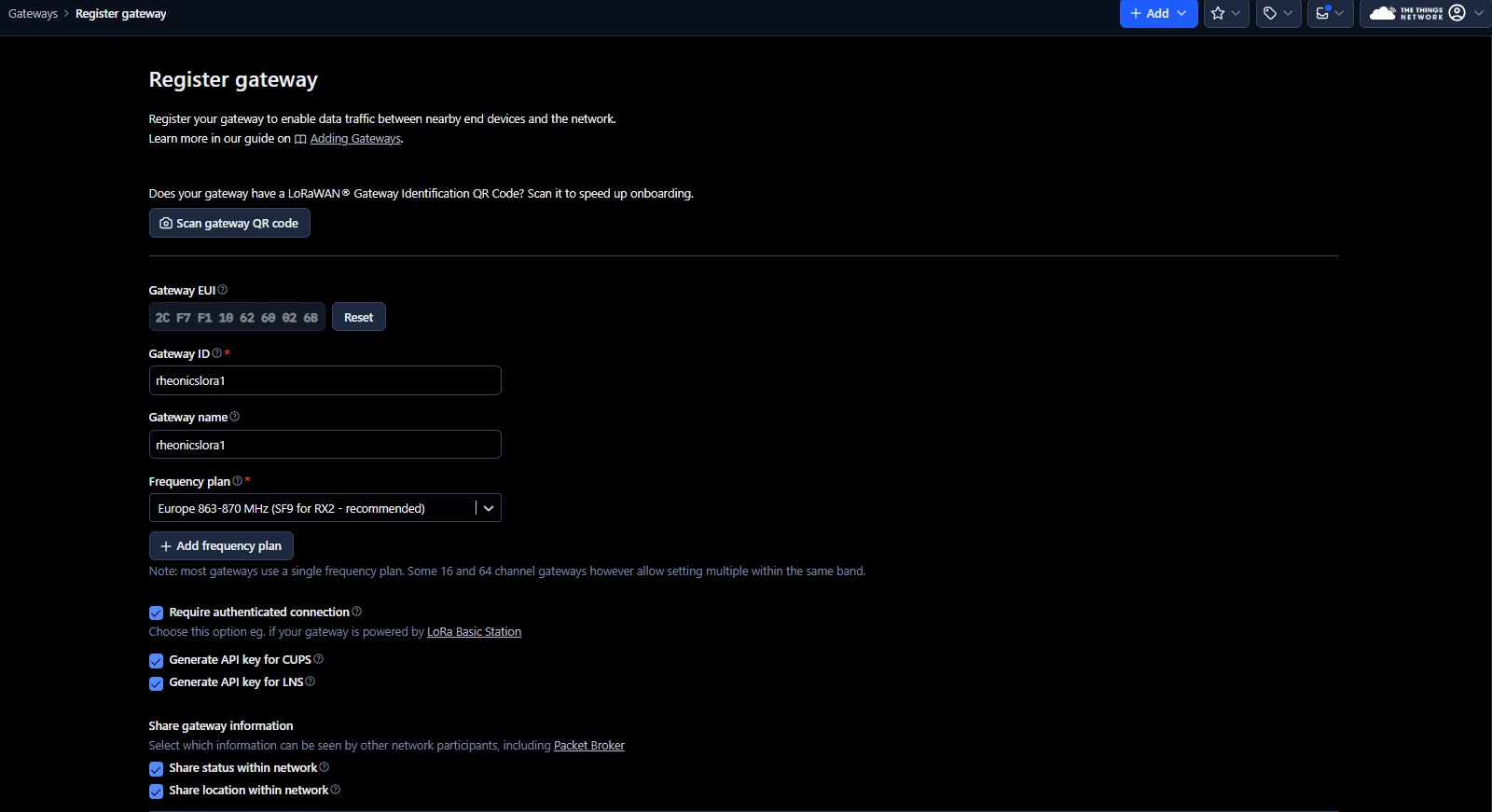
4. Fill the spaces with the following information:
- Gateway ID: e.g. rheonicslora1
- Gateway name: e.g. rheonicslora1
- Frequency plan: LoRaWAN operates on different frequency bands because it follows certain rules depending on the geographic area. The frequency plan selected in The Things Stack should match the SenseCAP M2 version. In this case, the EU868 version is being used, so the frequency plan EU863–870 must be selected in The Things Stack.
- Require authenticated correction: ✅
- Generate API key for CUPS: ✅
- Generate API key for LNS: ✅
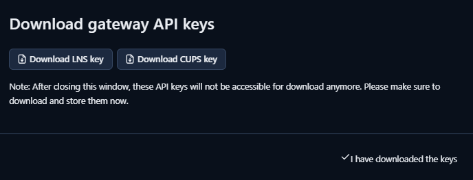
5. Next, make sure to download the gateway API keys (LNS and CUPS). These keys are randomly generated by The Things Stack and are used to verify the identity of the gateway.
|
6. Click on API keys in the gateway menu
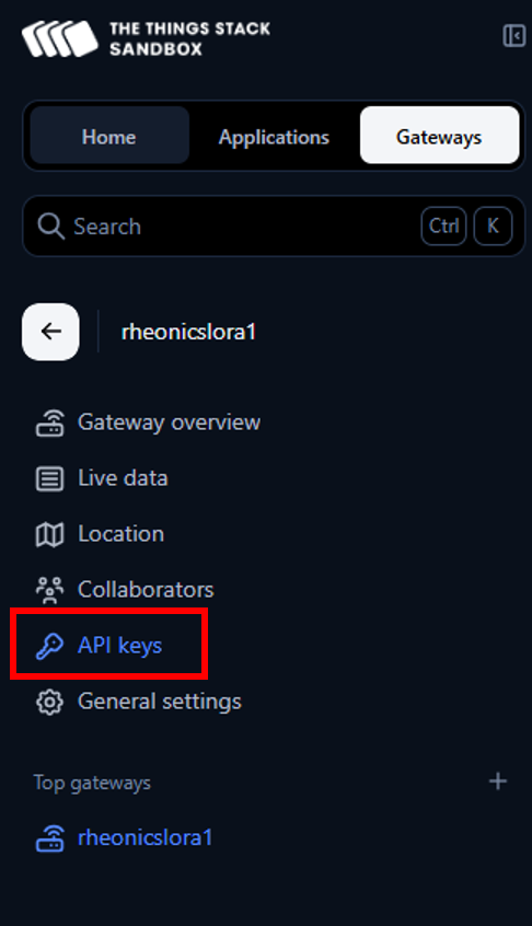
7. The LNS and CUPS keys generated previously should appear.
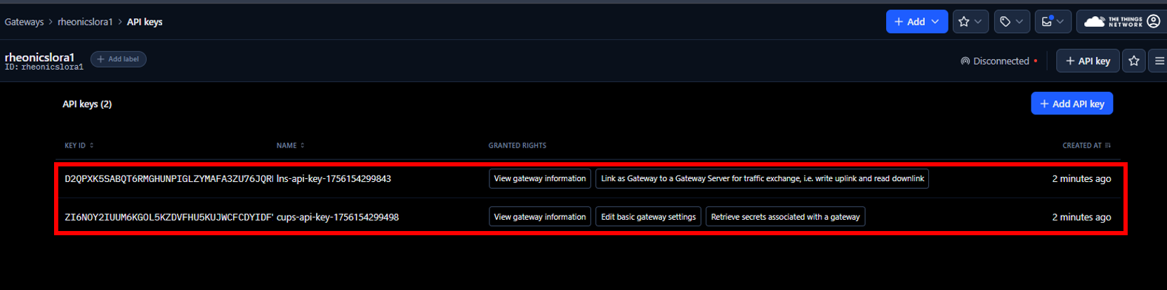
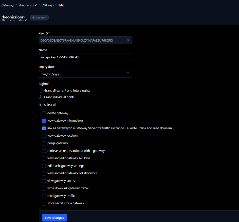
8. Click on the lns-api-key to view its configuration. This shows the rights assigned to the key, which allow the gateway to exchange information with the LoRaWAN Network Server and view gateway information. Make sure the rights shown in the following image are selected.
9. Click on the cups-api-key to view its configuration. This shows the rights assigned to the key, which allows viewing gateway information, retrieving secrets of the gateway, and editing basic gateway settings. Make sure the rights shown in the following image are selected.
 Figure 11: CUPS key configuration
3. SenseCAP M2 Multi-Platform Gateway Web Server Configuration
The SenseCAP M2 Gateway configuration can be done through the web server of the device.
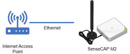
3.1. Connection of SenseCAP M2 Multi-Platform to the Internet
In this article, the SenseCAP M2 is connected using an Ethernet Cable to a Wi-Fi router to access the internet, as shown in the following diagram.
3.2. Enter SenseCAP M2 Web Server
1. To access the Web server, enter the device’s IP address into a web browser. To know the device’s IP address, use an IP scanner. Make sure the SenseCAP M2 and the computer are connected to the same network to ensure it appears in the scan.
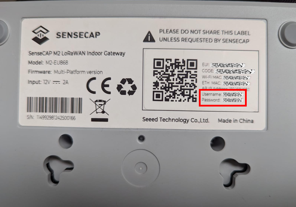
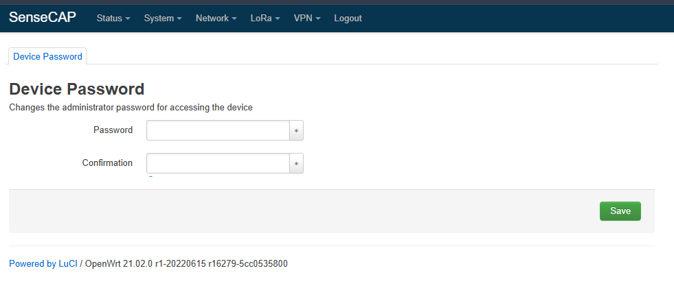
2. Enter the credentials found in the device label.
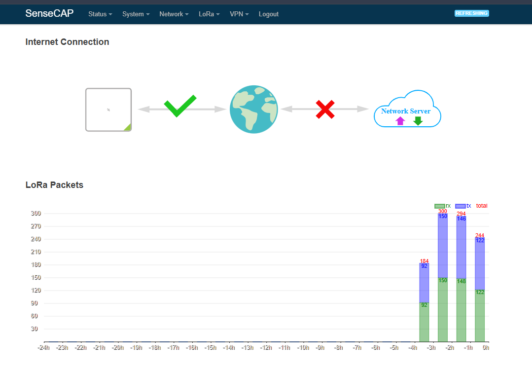
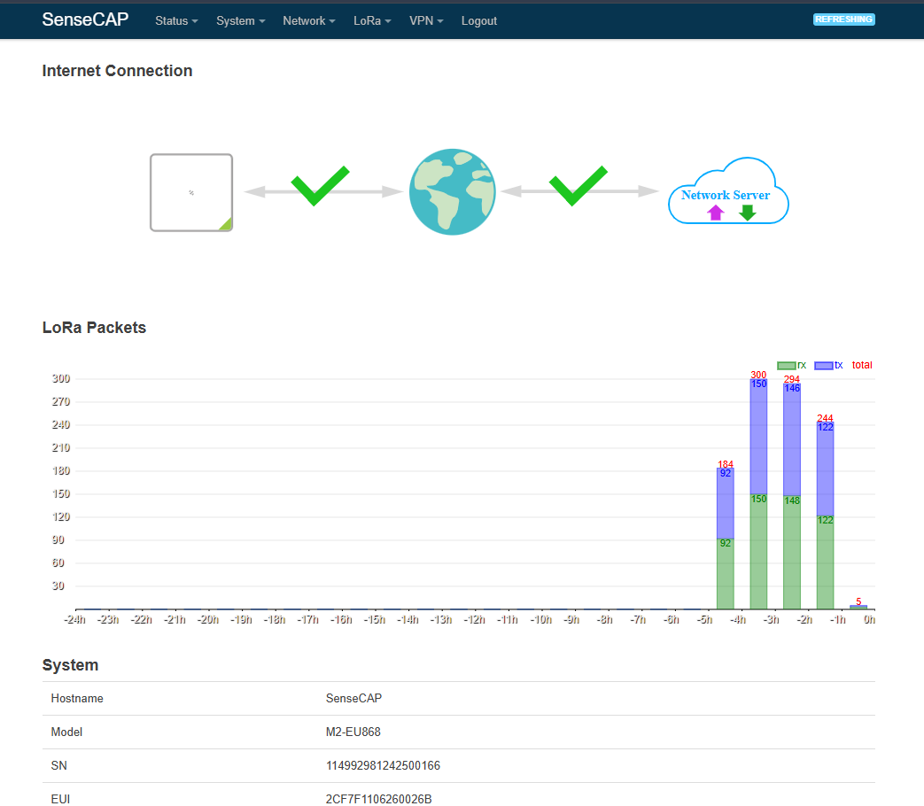
3. The web server appears as shown below when the internet connection is successful and the gateway LED turns green.
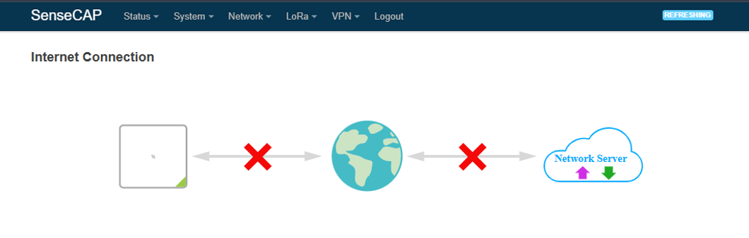
4. In case the gateway does not have an internet connection, verify that the Ethernet cable is securely connected between the SenseCAP M2 and the router, and ensure that the router provides internet access.
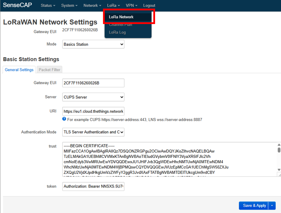
5. After the internet connection is established, select LoRa → LoRa Network from the top menu and configure with the following parameters:
- Mode: Basics Station
- Gateway EUI: found in the device label
- Server: CUPS server
- URI: for CUPS it is https://server-address:443. In this guide, Europe 1 cluster is used from the TTN console, so the URI is https://eu1.cloud.thethings.network:443
- Authentication Mode: TLS Server Authentication and Client Token
- trust: download the minimal certificate list from Root Certificates, then copy the data content of the certificate file
- token: Authorization: Bearer <CUPS API KEY> (downloaded previously during gateway creation on TTN)
6. Next, go to LoRa>>Channel Plan.
 Figure 18: Channel Plan menu
7. Select the same region configured for the gateway on The Things Stack, in this case, EU863-870.
 Figure 19: Channel Plan - Region configuration
8. After a few minutes, the gateway should connect successfully, and the following appears on the web server, indicating that it is connected to the internet and the network server.
9. Back to the gateway section on The Things Stack, the status of the gateway should appear as connected.

To use a LoRaWAN/Modbus TCP Master Converter for Remote Data Visualization of Rheonics Sensors refer to Using LoRaWAN/Modbus TCP Master Converter for Remote Data Visualization of Rheonics SensorsTo use a LoRaWAN/RS485 Converter for Remote Data Visualization of Rheonics Sensors refer to Using RS485-LN LoRaWAN Converter for Rheonics Sensors Remote Data Visualization
4. References
- LoRaWAN Fundamentals
- The Things Network Console
- Root Certificates
- What are LoRa and LoRaWAN?
- End Device Activation
- Connecting to TTN
- Regional Parameters