What products are involved?
This article is based on using Rheonics Sensor Module Electronics (SME), SenseCAP M2 Gateway, and the RS485 to LoRaWAN Converter.
What is the purpose of this article?
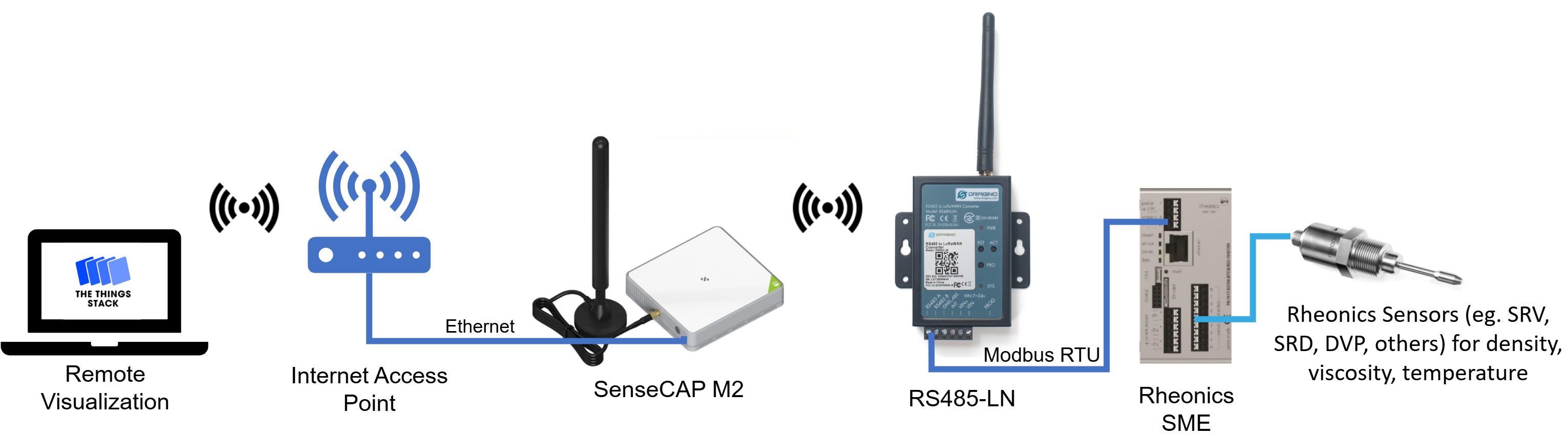
This article describes the process of integrating Rheonics sensors with the RS485-LN converter and the SenseCAP M2, so data can be transmitted wirelessly and visualized remotely via The Things Network.
1. Overview
LoRaWAN is a long-range, low-power communication protocol designed for transmitting sensor data over wide areas. In this article, the RS485-LN converts data from the SME via Modbus RTU and converts it into LoRaWAN messages. These messages are then sent to the SenseCAP M2 gateway, which is connected to the Internet and sends the data to The Things Network (TTN) or other LoRaWAN network servers. TTN is a LoRaWAN ecosystem that includes The Things Stack (TTS), a LoRaWAN network server that enables remote data access. Once received, the data can be decoded and can be visualized remotely.
Following this setup, Rheonics sensors can transmit sensor values wirelessly and be monitored in real time from anywhere through The Things Stack server.
To configure the SenseCAP M2 LoRaWAN gateway refer to the following article Configuring LoRaWAN Gateway for Remote Data Visualization of Rheonics Sensors2. RS485-LN Configuration
The RS485-LN configuration needs to be done in The Things Stack (TTS) and using the Dragino RS485 Configure Tool.
2.1. Configuration in The Things Stack (TTS)
1. Enter The Things Network Console and access the account.
2. Select Create application
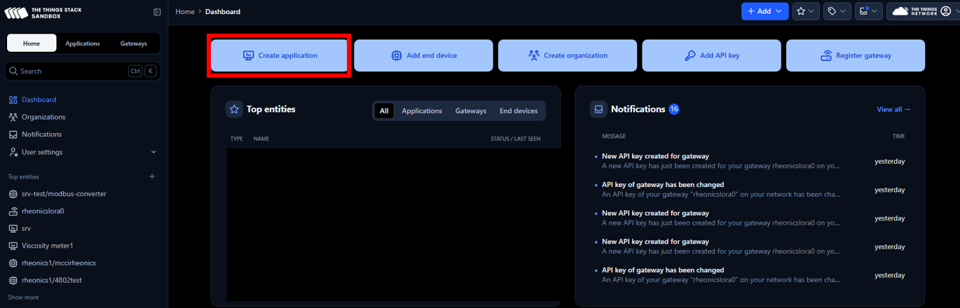
Figure 2: Application creation
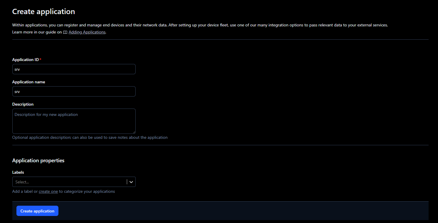
3. Add a name and ID for the new application
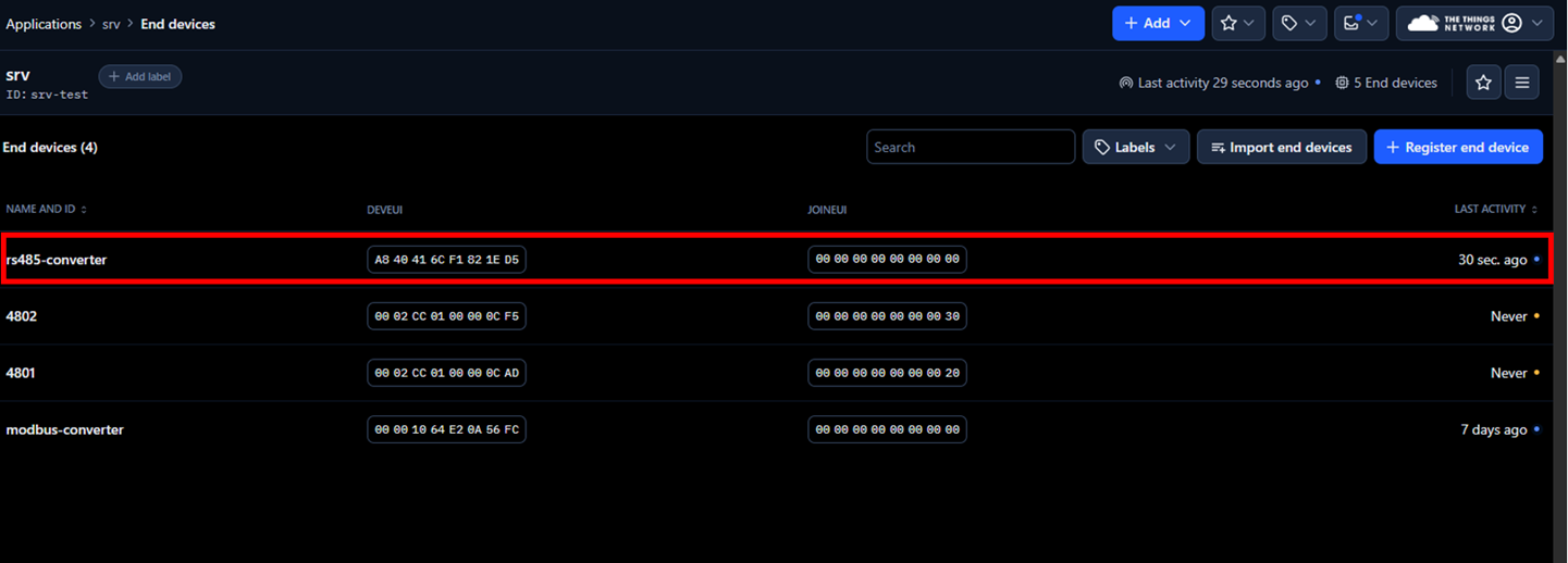
4. Next, go to the application, select End devices, and click on Register end device
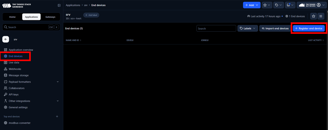
Figure 4: End device registration
5. Register the end device with the following parameters
- Frequency plan: Select a Frequency plan that is the same as the one specified in the device and the SenseCap M2 so it is compatible. In this case, Europe 863-870 MHz (SF9 for RX2 - recommended)
- LoRaWAN version: LoRaWAN Specification 1.0.3
- Additional LoRaWAN class capabilities: Class C (Continuous)
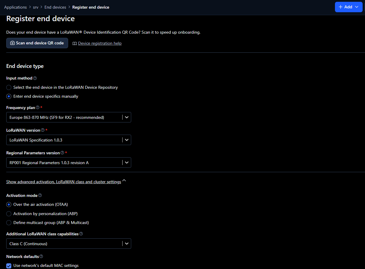
Figure 5: End device configuration
6. In the Provisioning information section, fill with the following and click on Register end device.
- JoinEUI: e.g. 00 00 00 00 00 00 00 00 - This identifies the Join Server, which handles the initial communication between the end device and TTS. It is usually assigned by the device manufacturer, but it can also be set by the user. If no JoinEUI is provided, a value of all zeros can be used if the Join Server supports it. It is possible to use the same JoinEUI for different end devices, but the DevEUI should be unique per end device.
- DevEUI: from RS485-LN label
- AppKey: generate a random key (necessary for the RS485-LN to be able to connect to TTS)
- End device ID: e.g. RS485-converter
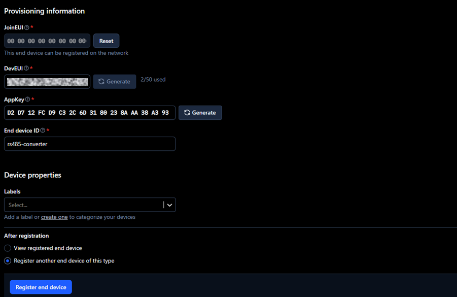
Figure 6: End device configuration - Provisioning information
2.2. RS485LN Configuration using Configuration Tool software
1. Connect the RS485LN to a PC using a USB-TTL Adapter and the Program Cable of the RS485-LN as the following diagram.
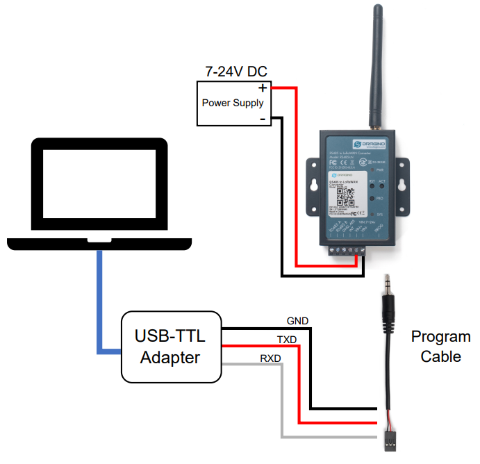
Figure 7: Diagram connection for RS485-LN configuration
2. Download the configuration tool from the next link Dragino RS485 Tool and select the latest version.
3. Open the Configuration Tool, select the COM of the UART to USB converter and Baudrate 9600. Click on Connect serial port.
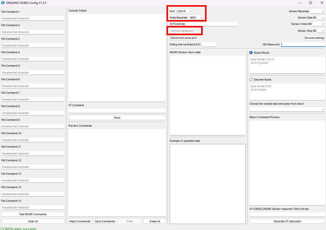
Figure 8: Configuration Tool
4. Enter the RS-485 parameters that can be found in Connecting Modbus RTU (RS-485) outputs, enter the default password, which is 123456, and click on Devices settings.
- Baudrate: 38400
- Sensor Data Bit: 8
- Sensor Check Bit: Odd
- Sensor Stop Bit: 1
- Polling interval time (Unit:S): 3
- NB-Password: 123456
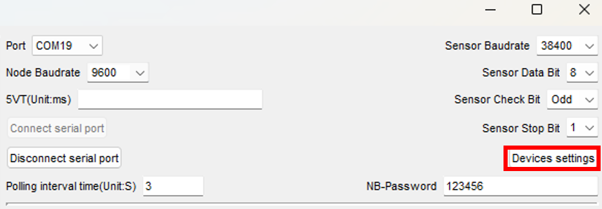
Figure 9: ModbusRTU parameters configuration
5. After clicking on the Devices settings button, the following should appear in the Console Output.
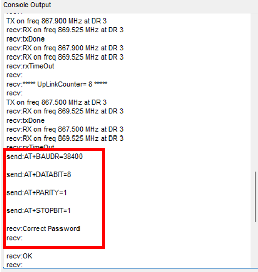
Figure 10: Modbus RTU parameters configuration
6. Next, send the command AT+APPEUI=APPEUI, replacing APPEUI with the JoinEUI selected in TTS, and click on send.
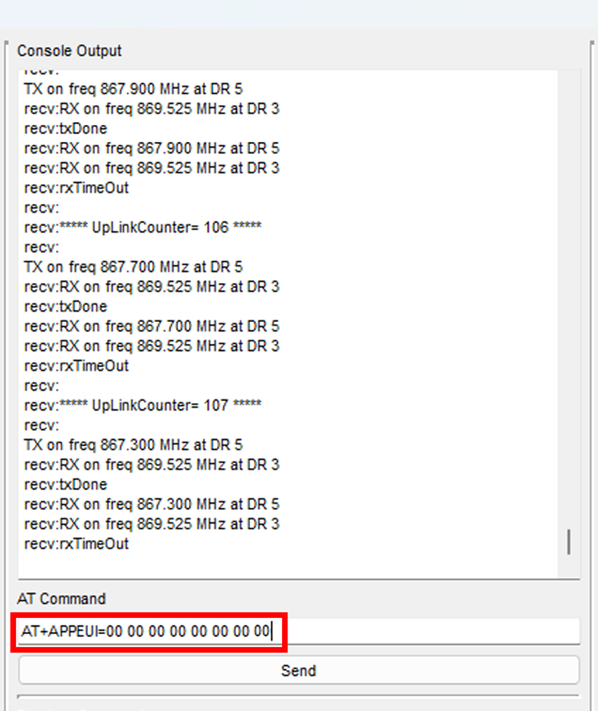
Figure 11: APP EUI configuration
7. An OK message should appear after sending the command.
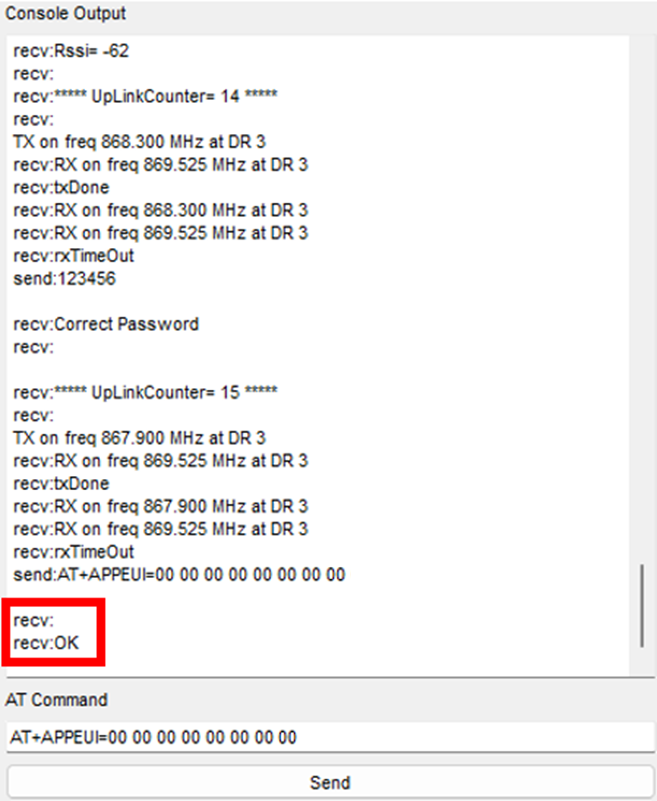
Figure 12: APP EUI confirmation message
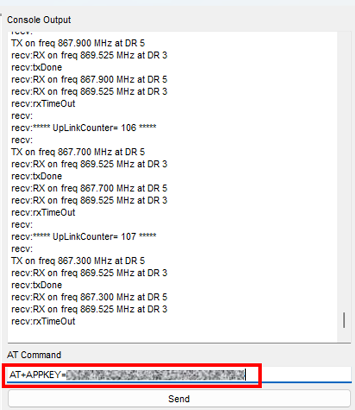
8. Next, send the command AT+APPKEY=APPKEY, replacing APPKEY with the AppKey generated in TTS, and click on send.
9. To check if the APPEUI and APPKEY have been uploaded successfully, send the following commands separately.
- AT+APPEUI=?
- AT+APPKEY=?
10. Click on the RST button on the device, and now the RS485-LN should be connected to TTS.
2.3. Modbus RTU Commands Configuration with RS-485 Configuration Tool software
The RS485-LN accepts up to 15 commands per connected device. Each command allows reading one parameter from the Rheonics sensor.
To read the registers and obtain the value desired, the command needed is composed of AA BB CC CC DD DD, where
- AA = Device ID
- BB = Function code
- CC CC = Start address of the register
- DD DD = Number of registers to read
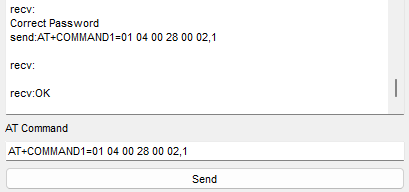
For example, to read the viscosity, the command to send would be: AT+COMMAND1=01 04 00 28 00 02,1. The last 1 indicates that the CRC is added automatically. Refer to the Modbus Input Registers to determine the rest of the parameters.
1. Open the Configuration Tool, connect to the corresponding COM, enter the default password, which is 123456, and click on Send. A message saying Correct Password should be returned. This allows sending the rest of AT Commands.
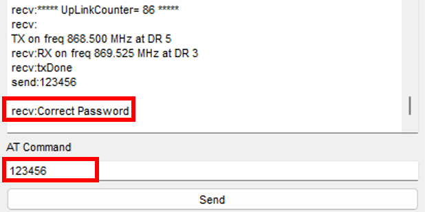
Figure 14: Sending RS485-LN password
2. In AT Command write AT+COMMANDX=XX XX XX XX XX XX,1 with the values wanted. This command can go from AT+COMMAND1 to AT+COMMANDF.
Here is the list of the commands for the 23 parameters. Change the first byte to the device ID required.
- Viscosity median = 01 04 00 28 00 02,1
- Density median = 01 04 00 30 00 02,1
- Temperature median = 01 04 00 38 00 02,1
- Kinematic viscosity = 01 04 00 40 00 02,1
- Density average = 01 04 00 48 00 02,1
- Viscosity raw = 01 04 00 50 00 02,1
- Density raw = 01 04 00 58 00 02,1
- Temperature raw = 01 04 00 60 00 02,1
- Resonant frequency = 01 04 00 68 00 02,1
- Compensated resonant frequency = 01 04 00 70 00 02,1
- Damping frequency = 01 04 00 78 00 02,1
- Coil temperature = 01 04 00 80 00 02,1
- Viscosity last good = 01 04 00 88 00 02,1
- Density last good = 01 04 00 90 00 02,1
- Mapped value (register 512) = 01 04 00 98 00 02,1
- Mapped value (register 514) = 01 04 00 A0 00 02,1
- Mapped value (register 516) = 01 04 00 A8 00 02,1
- Estimated temperature = 01 04 00 B0 00 02,1
- Temperature (PT1000 sensor) = 01 04 00 B8 00 02,1
- Calculated parameter from viscosity models = 01 04 00 C0 00 02,1
- Calculated parameter from density models = 01 04 00 C8 00 02,1
- Calculated parameter from concentration models = 01 04 00 D0 00 02,1
- Sensor cleanliness ratio = 01 04 00 D8 00 02,1
3. Sensor data visualization
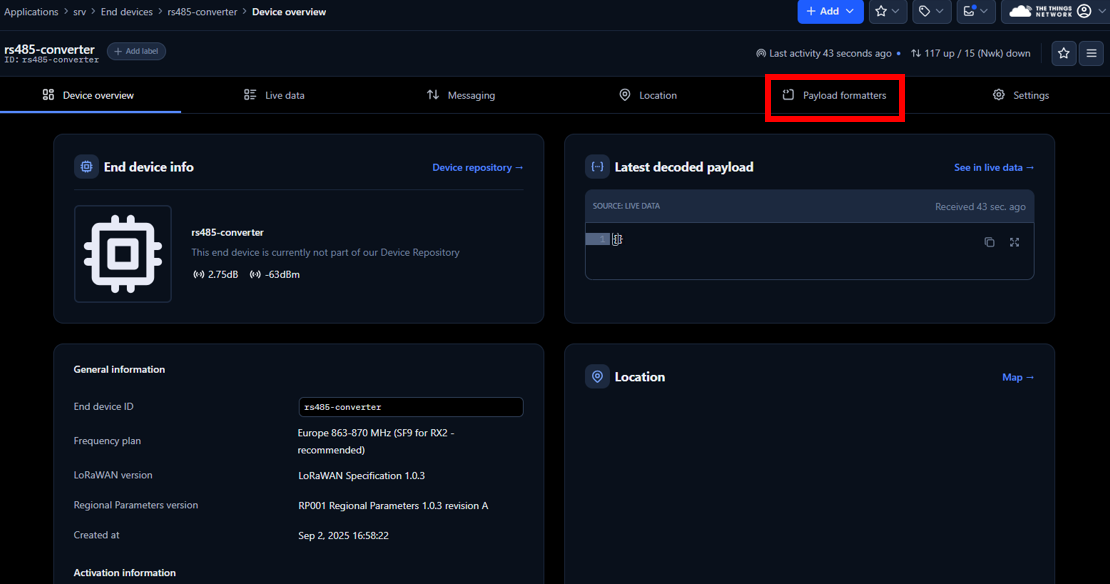
1. Enter The Things Stack, and click on the end-device created.
2. Select the Payload formatters Tab.
3. On Setup, select the following
- Formatter type: Custom JavaScript formatter
- Formatter code: Paste the following code to transform the data received into numbers for easy visualization.
function decodeUplink(input) {
let deviceId = input.bytes[0]; let bytes = input.bytes.slice(1); let data = { device_id: deviceId }; const parameterNames = [ "viscosity_median", // Parameter 0 "density_median", // Parameter 1 "temperature_median", // Parameter 2 "kinematic_viscosity", // Parameter 3 "density_average", // Parameter 4 "viscosity_raw", // Parameter 5 "density_raw", // Parameter 6 "temperature_raw", // Parameter 7 "resonant_frequency", // Parameter 8 "compensated_resonant_frequency", // Parameter 9 "damping_frequency", // Parameter 10 "coil_temperature", // Parameter 11 "viscosity_last_good", // Parameter 12 "density_last_good", // Parameter 13 "modbus_512_display", // Parameter 14 "modbus_514_display", // Parameter 15 "modbus_516_display", // Parameter 16 "estimated_temperature", // Parameter 17 "temperature_PT1000", // Parameter 18 "viscosity_model_calc", // Parameter 19 "density_model_calc", // Parameter 20 "concentration_model_calc", // Parameter 21 "sensor_cleanliness_ratio" // Parameter 22 ]; function bytesToFloat32(byteArray) { let buffer = new ArrayBuffer(4); let view = new DataView(buffer); byteArray.forEach((b, i) => view.setUint8(i, b)); return view.getFloat32(0, false); } for (let i = 0; i < bytes.length; i += 4) { let paramIndex = i / 4; if (paramIndex < parameterNames.length) { let paramName = parameterNames[paramIndex]; let floatValue = bytesToFloat32(bytes.slice(i, i + 4)); data[paramName] = isNaN(floatValue) ? "NaN" : parseFloat(floatValue.toFixed(6)); } }
return { data: data, warnings: [], errors: [] }; } |
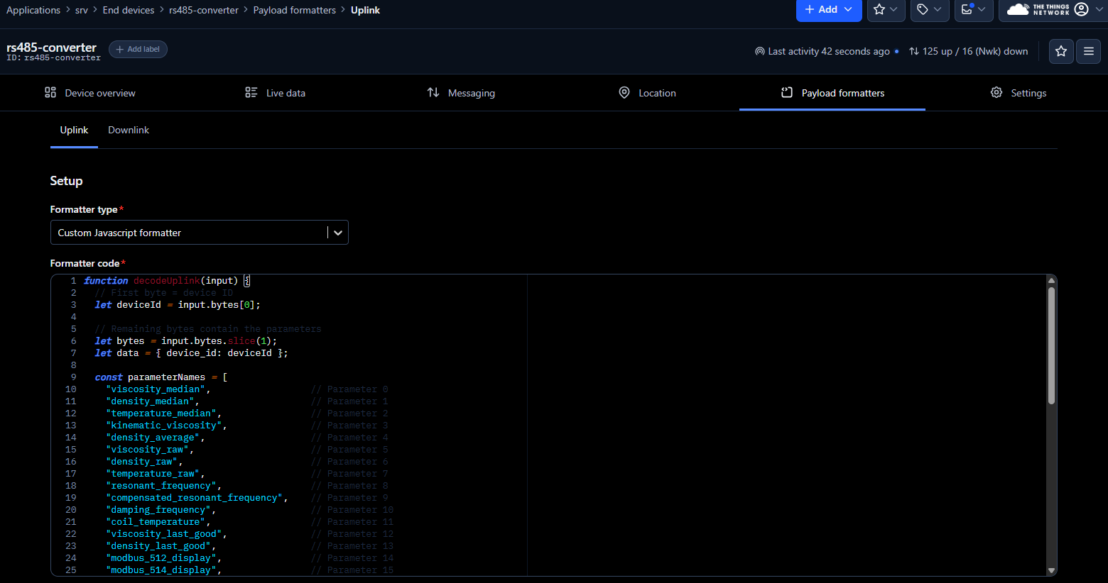
Figure 18: Payload formatters configuration
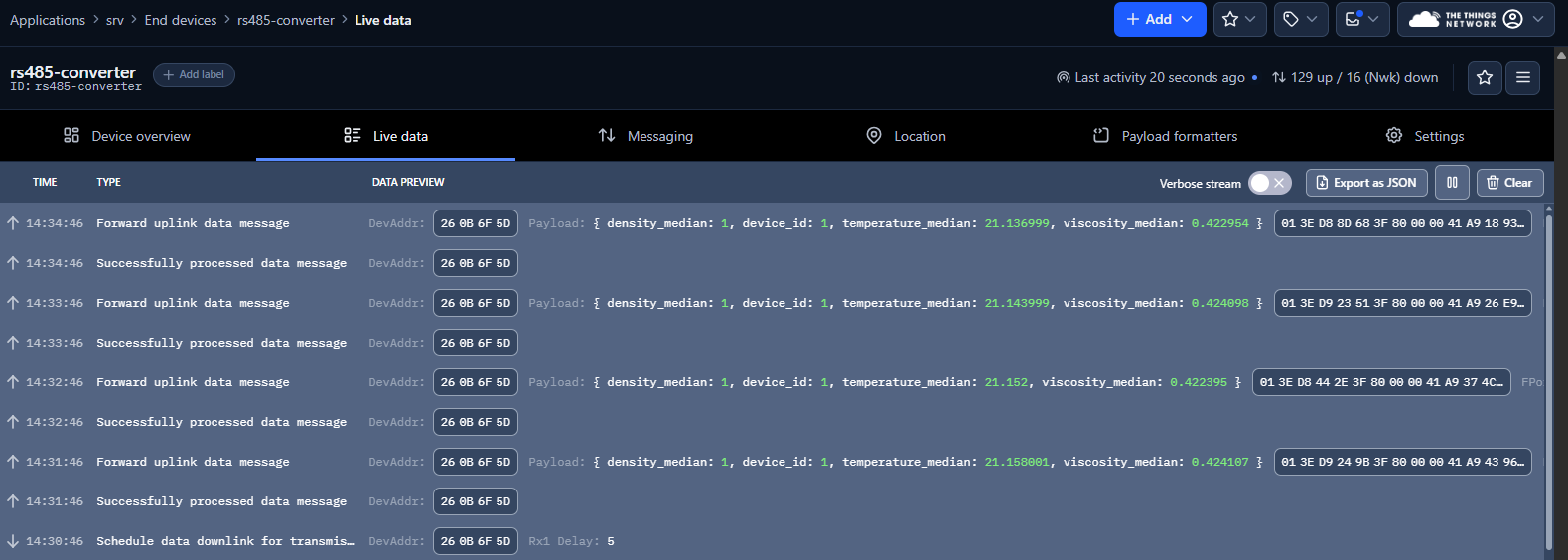
4. Select Live Data Tab to visualize the parameters obtained from Rheonics SME.
4. References
- Modbus RTU
- The Things Network Console
- Dragino RS485 Tool
- RS485-LN – RS485 to LoRaWAN Converter User Manual
- End Device AT Commands and Downlink Command