What products are involved?
SRV – Inline Viscosity Meter | SRD – Inline Density & Viscosity Meter | Ignition SCADA | Siemens S7 PLC (S7-300 / S7-400 / S7-1200 / S7-1500)
What is the purpose of this article?
This article provides a guide on how to use Ignition SCADA with Siemens S7 PLCs (S7-300, S7-400, S7-1200, and S7-1500) using the native S7 driver over TCP/IP. By establishing this connection, users can read and visualize real-time measurements from Rheonics sensors connected to the Siemens PLC.
TABLE OF CONTENTS
- 1. Overview
- 2. Prerequisites
- 3. Ignition Gateway Setup
- 4. Creating Tags (Manual Addressing)
- 5. Address Syntax Reference
- 6. Visualization and Analysis
1. Overview
Rheonics sensors (e.g. SRV, SRD) provide real-time fluid property measurements for process monitoring and control across a wide range of industrial applications. The sensors connect to the Rheonics Sensor Module Electronics (SME), which can be connected to a Siemens PLC. The PLC acquires the sensor measurements and stores them in its memory, making the data available to external systems such as SCADA platforms.
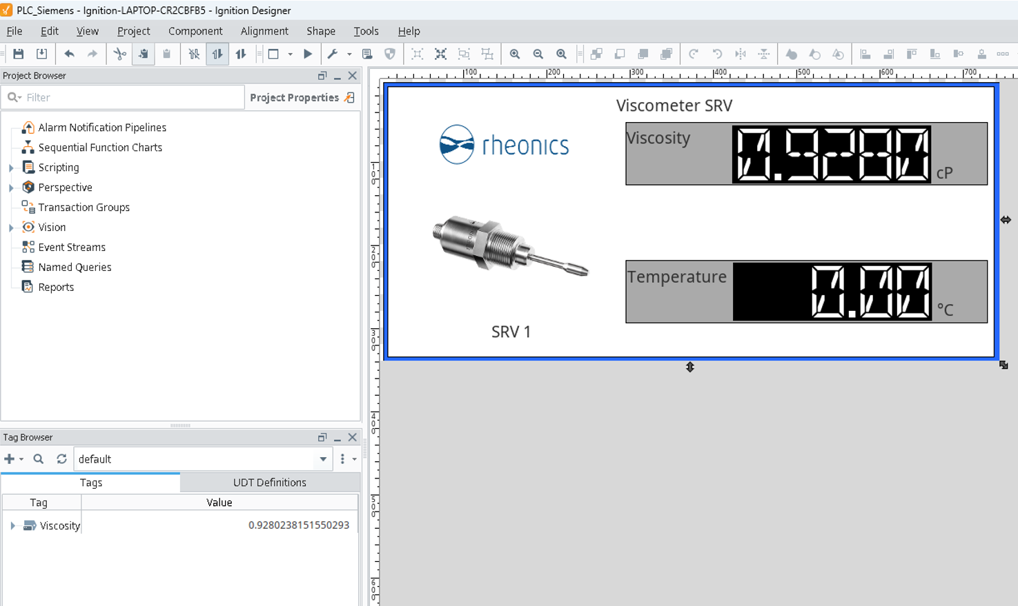
Using Siemens' native S7 communication protocol over TCP/IP, Ignition can establish a connection to the Siemens PLC and read the stored Rheonics measurement values. This article demonstrates how to configure Ignition to communicate with a Siemens PLC using the native S7 driver, create OPC tags for Rheonics sensor measurements, and display the data on an Ignition dashboard as shown in Figure 1.
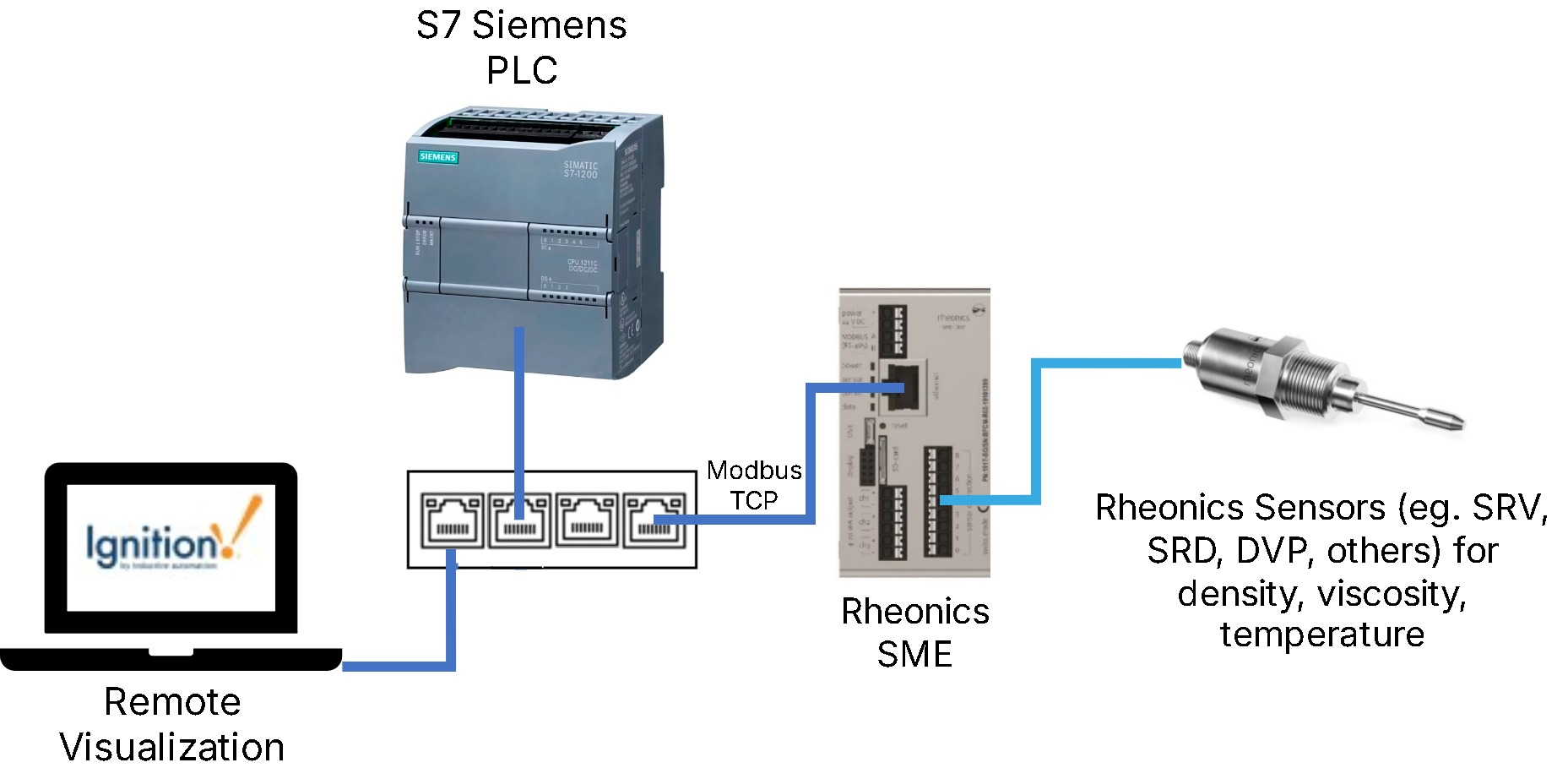
| For SME network wiring and Modbus TCP configuration, check: Connecting Rheonics SME to Modbus TCP. |
2. Prerequisites
2.1 Supported Devices
Ignition's native Siemens S7 driver connects over Ethernet (TCP/IP) to the following controller families:
- S7-300
- S7-400
- S7-1200
- S7-1500
2.2 S7-1200 and S7-1500 Considerations
Only global DBs can be accessed.
Reading/writing not supported for timer (TM) and counter (CT) areas.
Optimized block access must be turned off.
![Figure 2: Disabling Optimized block access on an S7-1200/1500 data block. [1]](https://s3-ap-south-1.amazonaws.com/ind-cdn.freshdesk.com/data/helpdesk/attachments/production/81193467361/original/kNT6OxDMJCh6VFRMfPNefbNyp146MGbVGA.png?1783630120)
![Figure 3: Selecting Full access under CPU protection settings. [2]](https://s3-ap-south-1.amazonaws.com/ind-cdn.freshdesk.com/data/helpdesk/attachments/production/81193467363/original/TAa2xY_vxNZYGhZEPWmOM0GRXuZf3BdmXw.png?1783630153)
3. Ignition Gateway Setup
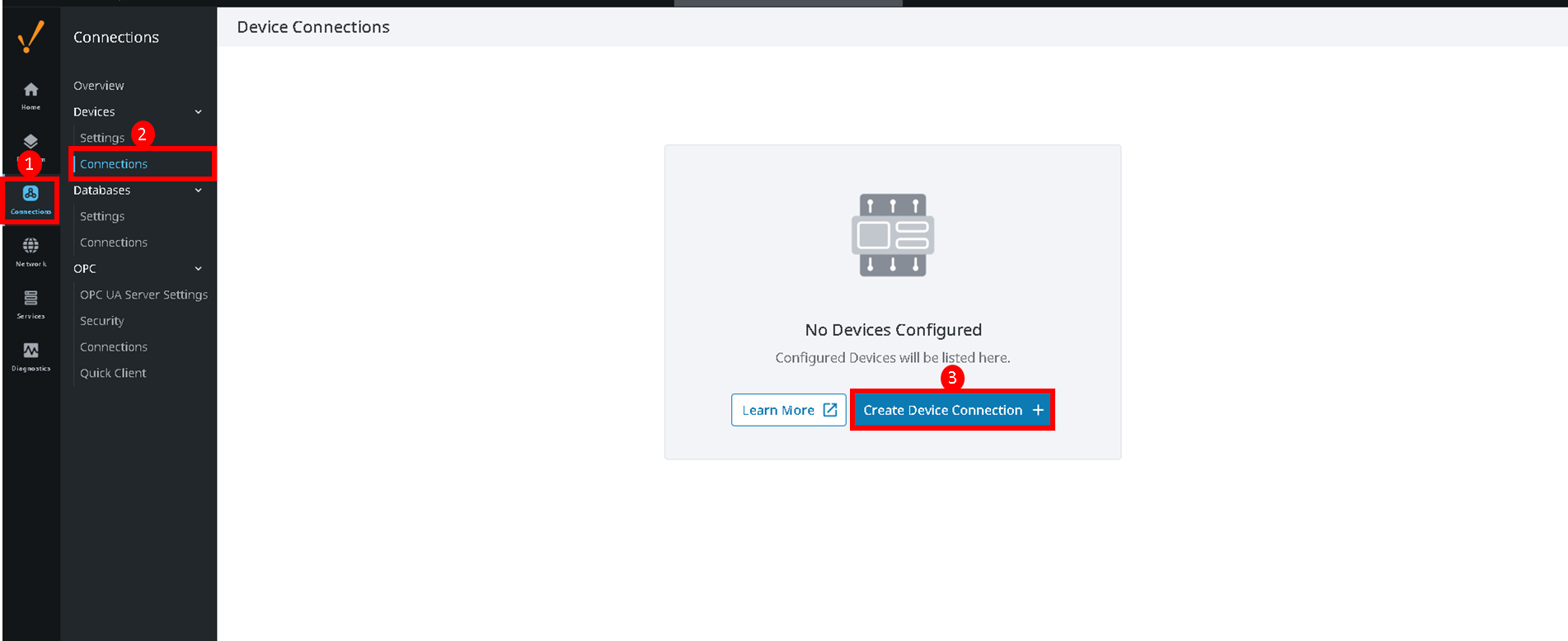
1. Open the Ignition Gateway webpage and navigate to Config > Connections > Devices, then click Create Device Connection.
2. Select the driver matching the PLC in use. In this case, Siemens S7-1200.
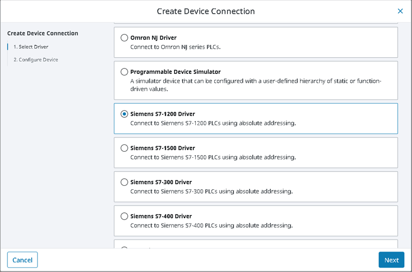 Figure 5: Selecting the Siemens S7-1200 driver.
3. Configure the device parameters:
- Name: e.g. PLC_Rheonics.
- Hostname: the PLC's IP address.
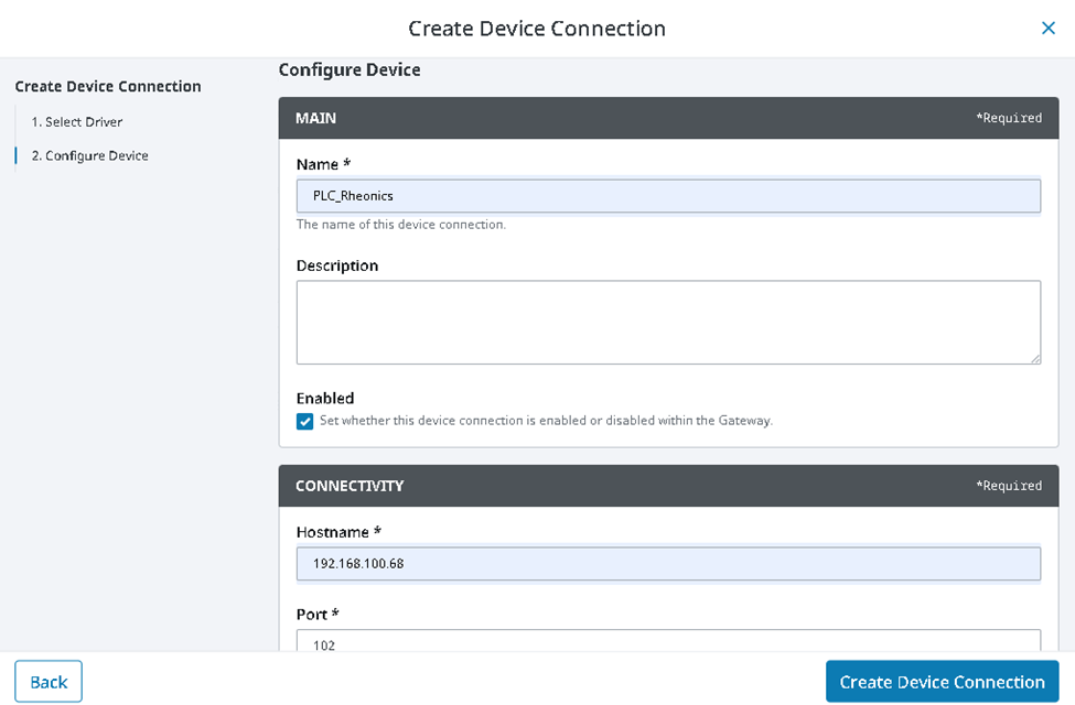
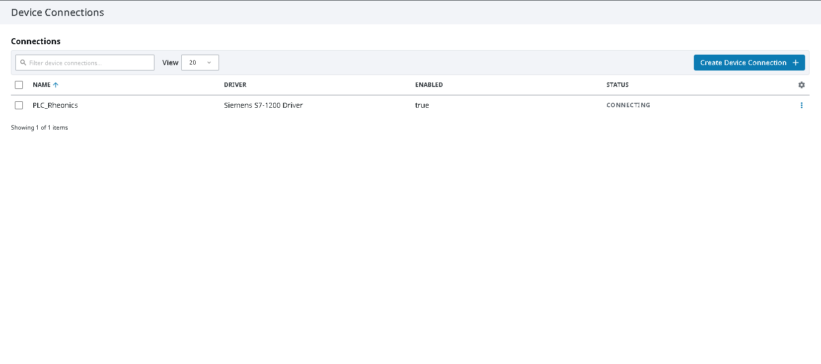
4. Click Create Device Connection. The status should change to Connected.
4. Creating Tags (Manual Addressing)
The S7 protocol does not support tag browsing, so tags must be created manually.
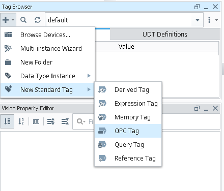
1. Open the Ignition Designer, click the + icon in the Tag Browser, and select New Standard Tag > OPC Tag.
2. Fill in the tag properties:
- Name: e.g. Viscosity.
- Value Source: OPC.
- Data Type: Float.
- OPC Server: Ignition OPC UA Server.
- OPC Item Path:
[DeviceName]Area,DataType+Offset.
In this example, the OPC Item Path has the following structure:
- Siemens PLC Driver: name of the device connection, e.g.
[PLC_Rheonics]. - Area:
DB10(data block 10). - Data Type:
REAL. - Offset:
0.
Combined, this gives an OPC Item Path of: [PLC_Rheonics]DB10,REAL0
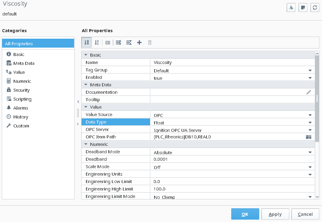
In this article, since the Siemens PLC communicates with the Rheonics SME via Modbus TCP, the value is read from where the PLC's Modbus client (MB_CLIENT) logic wrote the polled value in the program. In this example, that's Data Block 10, offset 0. |
5. Address Syntax Reference
5.1 Area Syntax
| Area | Syntax |
|---|---|
| Data Blocks | DBn (n = data block number) |
| Inputs | I |
| Outputs | Q |
| Flags | M |
| Timers / Counters | T / C |
5.2 Data Type Syntax
| Data Type | Syntax | Notes |
|---|---|---|
| Bit | X | No sign. |
| Byte | B | Unsigned. |
| Char | C | Signed. |
| Word | W | Unsigned. |
| Int | I | Signed |
| DWord | D | Unsigned. |
| DInt | DI | Signed. |
| Real | REAL | Signed |
| String | STRING | No sign. |
| Date_And_Time | DT | Only supported on S7-300, S7-400, and S7-1500. |
| LInt | LI | Signed. Only supported on S7-1500. |
| LReal | LREAL | Signed. Only supported on S7-1200 and S7-1500. |
6. Visualization and Analysis
Once tags are active, drag them onto Ignition Designer components to visualize Rheonics sensor data.