
What is the purpose of this article?
This article explains how to connect a Rheonics Sensor Module Electronics (SME) to ThingsBoard Community Edition over Modbus TCP, poll the sensor's Modbus registers using the ThingsBoard Gateway, and display live SRV/SRD data on a ThingsBoard dashboard.
TABLE OF CONTENTS
- 1. Overview
- 2. ThingsBoard Setup
- 3. Gateway configuration
- 4. Modbus register reference
- 5. ThingsBoard dashboard
- 6. References
1. Overview
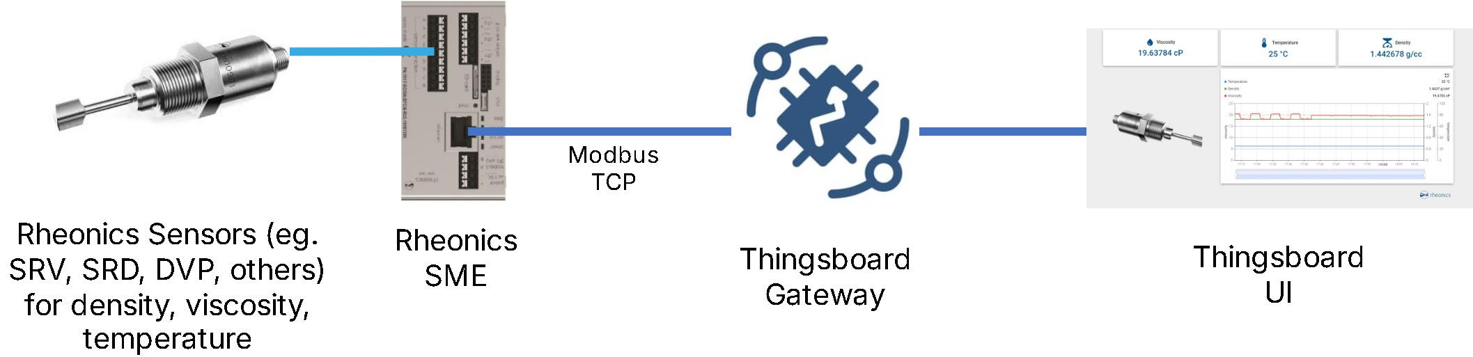
ThingsBoard is an open-source IoT platform for device connectivity, data collection, processing, and visualization. It can communicate with industrial devices over protocols such as Modbus TCP, which makes it a convenient platform for monitoring Rheonics sensors.
In this article, ThingsBoard Community Edition is configured to acquire data from Rheonics sensors via Modbus TCP, using the ThingsBoard Gateway, and to display sensor parameters in a real‑time dashboard.
2. ThingsBoard Setup
1. Install ThingsBoard by following the official Installation options documentation. This article uses ThingsBoard Community Edition installed via Docker, as described in Installing ThingsBoard CE using Docker (Windows).
2. After installing ThingsBoard, open a browser and navigate to http://localhost:8080, then log in as a Tenant Administrator. The default credentials are listed in the Docker installation guide linked above.

3. Gateway configuration
3.1 Create a gateway device
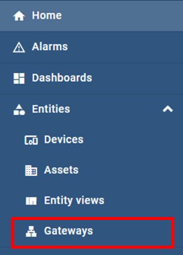
1. In ThingsBoard, navigate to Gateways.
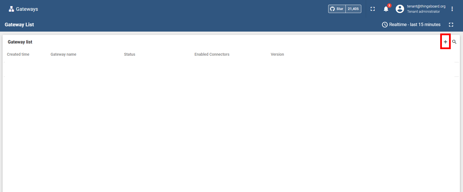
2. Select Add gateway.
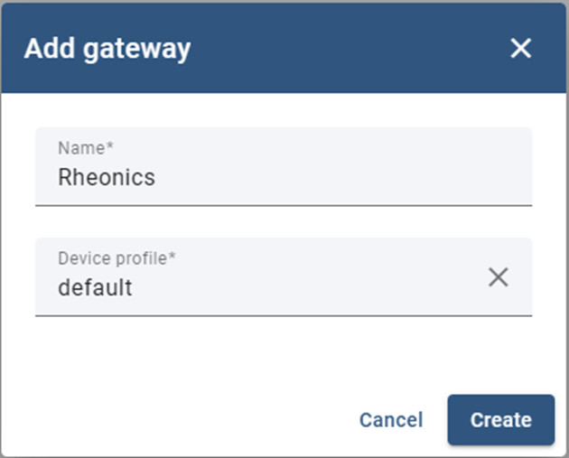
3. Enter a name for the gateway, select Default for the device profile, then click Create.
4. Download the configuration file from the launch command window.
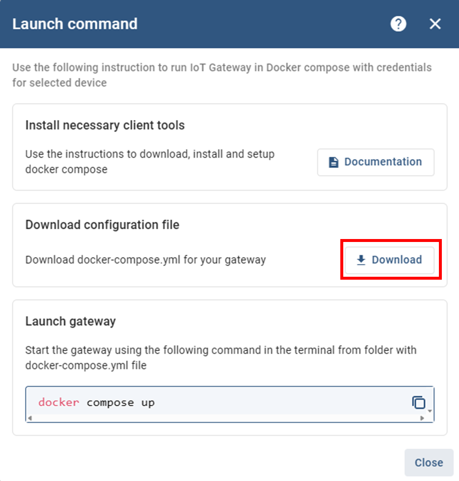
3.2 Start the ThingsBoard Gateway
1. In the folder that contains the docker-compose.yml file, open a terminal and run:
docker compose up
2. The gateway status should appear as active.
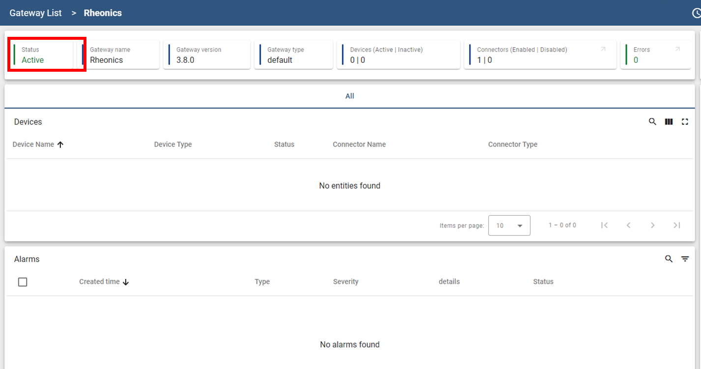
| ⚠ Important — port conflict: ThingsBoard Gateway uses MQTT port 1883 to communicate with the ThingsBoard server. Confirm this port is free on the host machine before starting the gateway, if it is already in use by another service, the gateway will fail to connect. |
3.3 Configure the Modbus connector
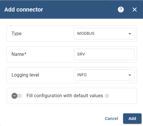
1. Click on Connectors configuration.
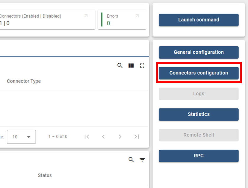
2. Add a new connector.
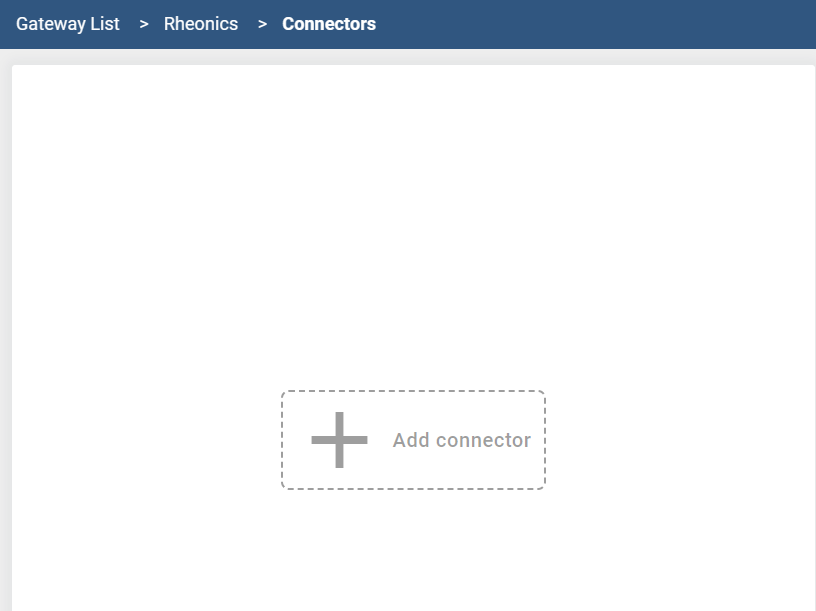
3. Fill in the connector with the following information:
- Type: Modbus
- Name: e.g. SRV
- Logging level: Info
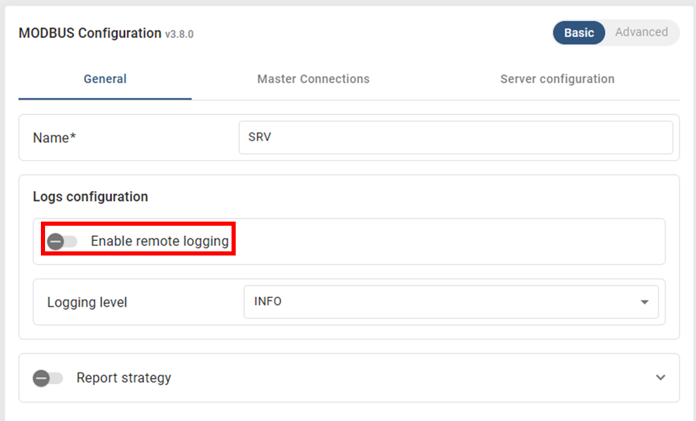
4. Disable remote logging.
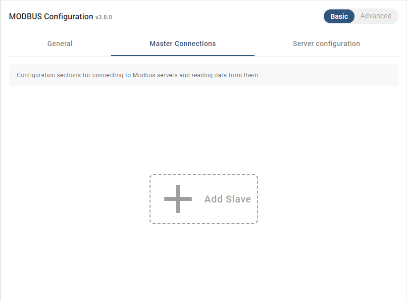
5. Under Master connections, add a slave.
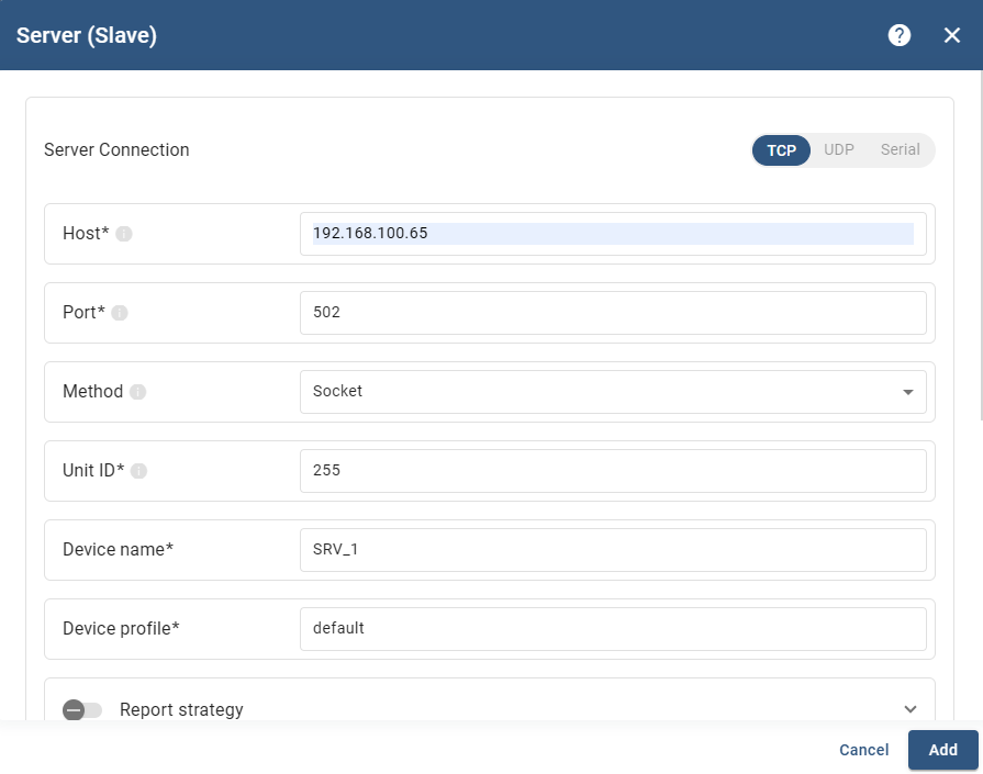
6. Fill in the following information:
- Host: IP address of the SME
- Port: 502
- Method: Socket (TCP framer)
- Unit ID: 255
- Device name: e.g. SRV_1
- Device profile: default
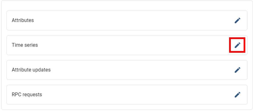
7. Add a time series by clicking the pencil icon to read an input register.
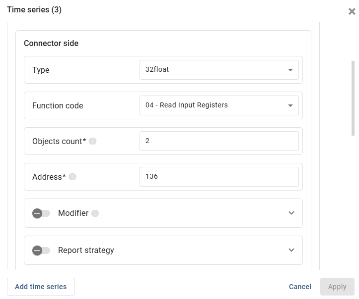
8. For example, to read viscosity:
- Key: name of the variable, e.g. viscosity
- Type: 32float
- Function code: 04 – Read Input Registers
- Address: 136
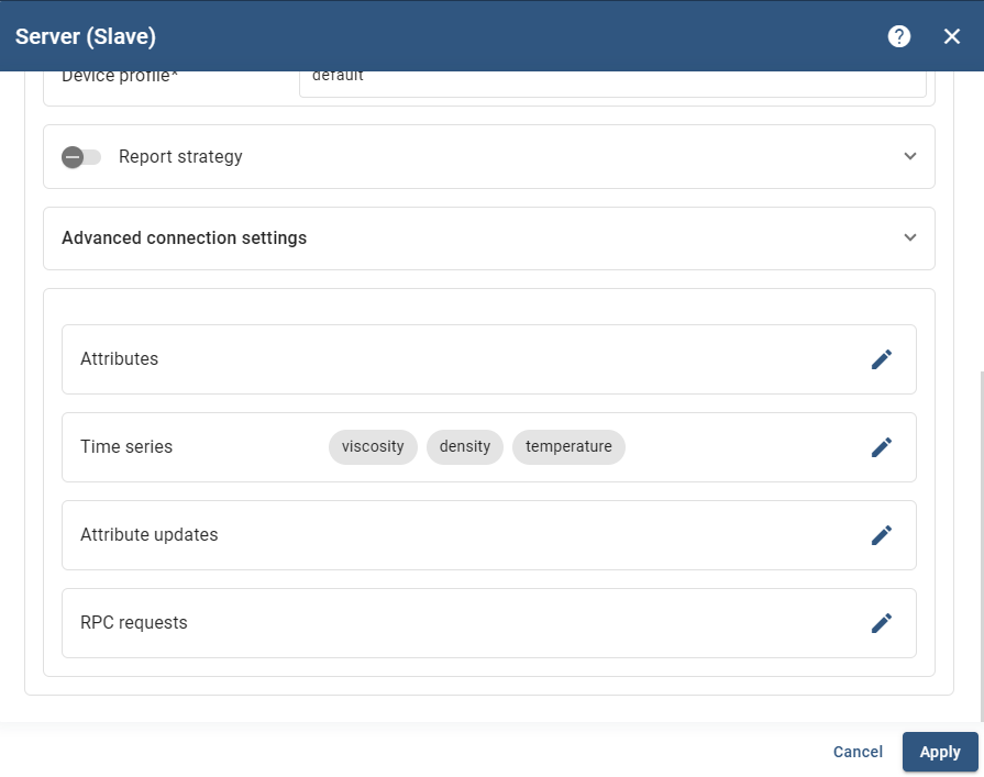
9. Click Apply and repeat this step to add any additional parameters needed — see the register reference in Section 4 for common examples.
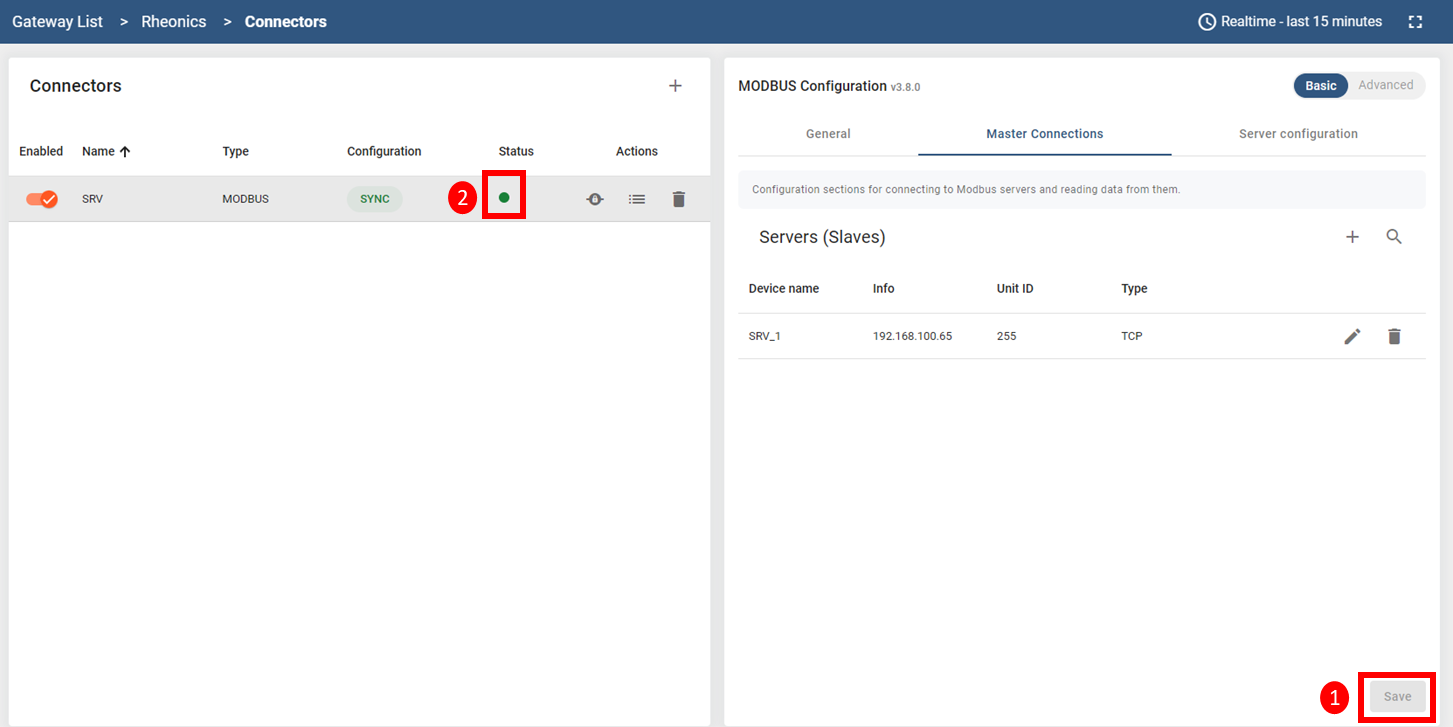
10. Click Save. The connector status should turn green.
11. Navigate to Devices.
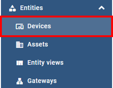
12. Two devices should now be visible: one for the ThingsBoard gateway itself, and one for the SRV.

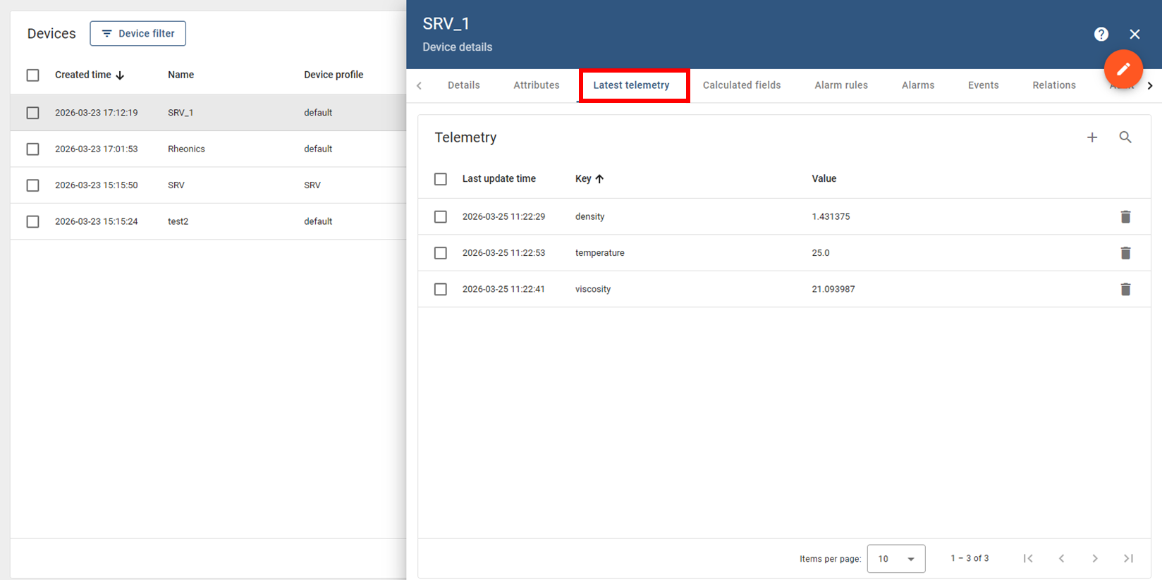
13. Click on the slave device, then open the Latest telemetry tab to confirm the parameters configured are visualized.
4. Modbus register reference
The table below lists commonly monitored Rheonics parameters and the corresponding Modbus input registers.
Table 1: Common Rheonics input registers
| Parameter | Protocol address | Register | Count | Description |
|---|---|---|---|---|
| Parameter 12 – Viscosity Last Good | 136 | 300137 | 2 (Float32) | Parameter 12 value as float. |
| Parameter 13 – Density Last Good | 144 | 300145 | 2 (Float32) | Parameter 13 value as float. |
| Parameter 2 – Temperature Median | 56 | 300057 | 2 (Float32) | Parameter 2 value as float. |
| → Check Modbus Input Registers for the complete list of registers available on Rheonics sensors. |
5. ThingsBoard dashboard
To simplify deployment, preconfigured dashboard templates are available for SRV and SRD sensors.
1. Navigate to the Dashboards section and click the + button.
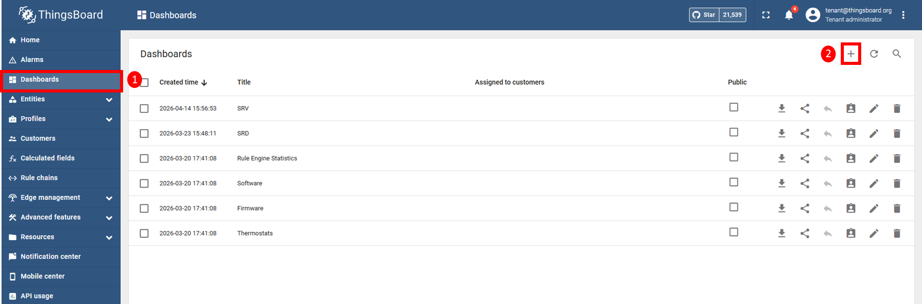
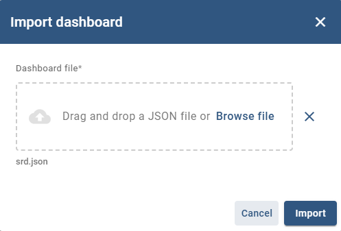
2. Click Import file and select the dashboard file attached in this article for the sensor (SRD or SRV).
3. Add the attached images to your ThingsBoard Image gallery to make them available for use in the dashboard. See Image Gallery for instructions on uploading and managing images.
4. Open the imported dashboard.
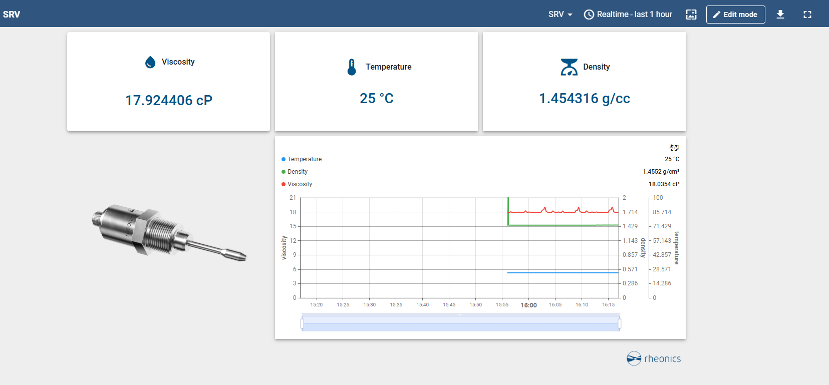
5. Enter edit mode and edit each widget.
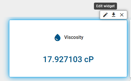
6. For each widget, select the configured device and the corresponding data key.
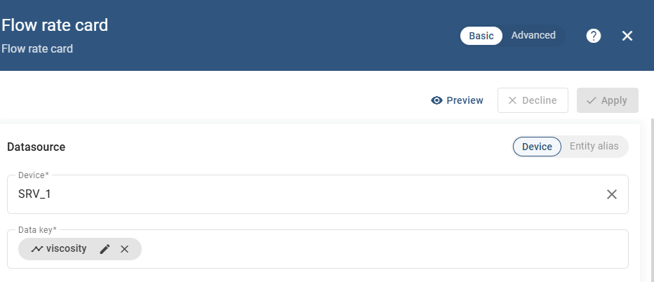
7. Repeat this process for the remaining widgets, then save the dashboard.
6. References
- What is ThingsBoard?
- Installation options | Docs | ThingsBoard
- Installing ThingsBoard CE using Docker (Windows)
- Modbus Connector Configuration | ThingsBoard IoT Gateway