What products are involved?SRV, SRD, DVM, DVP, SME-DRM, SME-TR/TRD.
For SME-DRM (DIN rail mount) transmitter. Visit our product page to learn more about the full features.
Visit Rheonics product page:Products » inline fluid viscometer and density meter
What is the purpose of this article?To give guidance and good practices when preparing Rheonics EX intrinsically safe sensor cable with a crimp of length 8mm and terminal diameter 1mm. The terminals of the SME are rated for wires of 0.2 - 1.5 mm2 i.e. AWG 24 - 16.
Normally, Rheonics provides the Ex cables completely assembled and ready for installation, so the user can omit the next sections and only focus on the proper wiring. For cases where the Ex cables are not delivered assembled with the M12 connector and pin ferrules (i.e. when Rheonics delivers a roll of cable for many custom lengths), follow the next sections.

1. Required tools
Tools
Crimping Tool
Crimping tools are used to deform materials and create connections. To connect wires together or to other connectors, crimping is commonly used in electrical work.

Precision Micro Wire Cutter
A wire cutter or cable cutter is a tool that cut wires and cables in a safe manner without damaging the insulation or conductors.

Measuring Tape
A Measure Tape is a tool used to measure length.

Stripping tool
Wire strippers are portable handheld tools used by workers, especially electricians, to remove the protective coating of electric wires for replacement or repair.

Knife
A tool used to cut wires or cables.

Soldering Equipment
A durable, permanent connection can be created by joining conductive metal elements with solder. Soldering machines are essential tools for building, modifying, and repairing electronics.

Hot air gun
Heat guns are devices that emit a jet of compressed air toward a particular point or surface.

BoM list
Item name | Manufacturer name | Manufacturer Part number | Vendor Part number | Reference |
|---|---|---|---|---|
Ferrule | RND | RND 465-00566 | 301-10-345 | |
Solder wire | RS PRO | 800-7661 | 800-7661 | |
Heat Shrink tube | HellermannTyton | 380-03005 | 711-4783 | |
Ex Sensor cable | Helu Kabel type | 14079 | 14079 | |
M12 Connector | Phoenix Contact | SACC-M12FS-8QO-0,5 SH | 1414611 |
|
Metal tape | 3M | 4312555 | 302-03-552 | https://www.distrelec.ch/en/aluminium-foil-tape-431-25mm-55m-silver-3m-4312555/p/30203552 |

Ferrule
Correct ferrule size must be selected based on the gauge of the wire, as a standard Rheonics uses ferrule with a pin length of 8mm and diameter of 1mm (cross-section 0.5mm2).

Solder wire
Solder wires are wires with a low melting point, used to create joints using a soldering iron.

Heat shrink tube
Heat shrink tubing is a common element in most electrical installations that protects wires from moisture, dust, abrasion, and sharp objects that might otherwise damage them.

Ex Sensor Cable
The SRV/SRD sensor is connected to its associated Zener diode barriers by means of a cable that has an 8-pole M12 connector on the sensor end.
The cable and connector selected must be rated for at least the highest ambient temperature at which the sensor will be used.

M12 connector of the sensor cable
Connector, Universal, 8-position, halogen-free, shielded, Socket straight M12, A-coded, Insulation displacement connection, knurl material: Zinc die-cast, nickel-plated, external cable diameter 5 mm ... 9.7 mm

Metal tape
This tape is commonly used to secure duct seams, connections, and joints. Additionally, it has excellent waterproof properties.

End result
Once all the steps are completed we are going to obtain our Ex sensor cable with the following three sections.

2. Probe side - Sensor cable preparation for M12 connectorRequired tools:
Knife
Measurement tape
M12 Connector
Metal tape
There is a video available from supplier showing the connection of the M12 connector in the cable, see: Circular connectors for data and signals – SACC QUICKON
Take the cable and cut the required length for your application. We recommend stripping out the cable sheath at 80mm from the end as a suitable length to prepare the cables for the M12 connector.

Since the sensor cable has an outer diameter of about 8.5 mm, the cable's shield must be fixed
with the provided metal tape as shown in the instructions for cable with a diameter over 6 mm.

After the cable shield has been fixed, the rest of the shield can be cut at the edge of the tape. Then pass all 8 wires of the cable through the connection body. Take care not to damage the insulation of the wires. Push the cable completely into the sensor connector to ensure proper contact with the cable shield.
The connector body has 8 color marked slits in the front. Pull each wire into the slit marked with its
color as shown in Figure 18.

Cut the remnant of each wire, so each wire is fixed in the available space.
 Figure 19. The connector body in front view after the wires have been shortened.
Close the sensor connector.

After the sensor connector has been mounted on the blue sensor cable, it can be connected to the M12 male port of the sensor probe.
3. SME electronics side - Sensor cable preparation for EX zener barriersRequirements:
Knife
Cutter
Strip the blue outer cable sheath on a length of 100 mm (4 in.).

After the stripping of the cable sheath, carefully loosen and then twist the cable shield.

Remove the plastic cover from the colored wires.

3.1. Preparing grounding cable
Requirements:
Soldering machine
Solder wire
Heat Shrink tube
Hot air gun
Take the twisted cable shield and cover it fully with a heat shrink.
Take the twisted cable shield and cover it fully with a heat shrink.

Crimp a ferrule to the ground cable end.
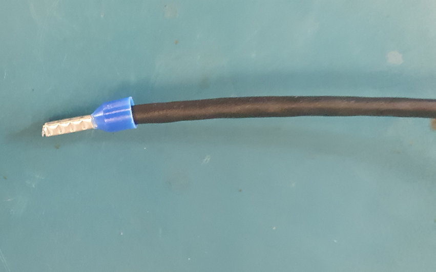
3.2. Installing crimpers in each sensor wire
Requirement:
Crimping tool
Your crimping tool should have a nest for inserting the terminal. After inserting in the correct slot, squeeze the crimp tool firmly and release it to get a long-lasting, tight fuse.
Unused wires should be neither stripped nor crimped. We recommend protecting the ends with a shrink tube to avoid the ends making any electrical contacts.
We recommend crimping the ferrules on 4 sides for the connection with the Zener barriers.
Twist the wire and Crimp them (Crimpers) using the Crimping Tool.

The green and yellow wires are not used to operate the sensor. They have to be connected to the
ground together with the shield of the cable. This means that they should be connected to the ground terminals of the Zener barriers.

Strip all eight wires on a length of 10 mm and put bootlace ferrules on the ends.

4. Ex zener barriers to SME connectionNext is the connection of the Zener barriers with the SME-DRM, the blue end is used to connect to the sensor that is installed in the hazardous area.

Requirement:
Various wires with crimped ends.
Zener barriers Z041x2 and Z757.
SME-DRM
Install the SME-DRM and the Zener barriers in a DIN-rail and prepare short wires to be used.

Next is to have a proper grounding, which could be either the DIN-rail or the ground available in the Zener barriers.

The wiring should be done the same as the wiring diagram shown in Figure 28 Part A. The end result should be as follow.

5. Ex sensor to zener barrierRequirement:
Ex Sensor cable with crimped ends.
Zener barrier Z041 x 2 and Z757
SME-DRM
This step starts with the wiring of each ferrule end with the connection of the Zener barrier, we need to connect each wire to the corresponding terminal in the Zener barrier based on this wiring diagram where the Part B represents the ferrule ends prepared.

The final result should look like this.

Note:
Typically SME-DRM is used for connection with EX barriers so both can be mounted inside a cabinet with DIN rails

However, it is also possible to put the EX barriers in another enclosure and connect to the SME-TR or SME-TRD using cable glands.
The barrier can also be used in an enclosure and a cable can be connected between barrier and the SME-TR/TRD through cable glands.

References:
[1] Crimping Pliers for Wire Ferrules
[2] Precision Micro Wire Cutter - Cutting Range: 28-14 AWG
[3] How To Read Measure Tape | Reading A Tape Measure | Measuring Tape Reading
[4] FD2810WS - Wire Cutting and Stripping Tool - 28AWG to 10AWG
[5] Uline Steel Knife in Stock - ULINE
[7] RS PRO EOT0202 500°C max Corded Heat Gun, Type C - EuroPlug
[9] RS PRO Wire, 0.71mm Lead solder, 183°C Melting Point
[11] Productdetails | HELUKABEL
[12] SACC-M12FS-8QO-0,5 SH - Connector - 1414611 | Phoenix Contact
Recommended articles:
Best Practices for Cable Installation
Nothing is happening when I plug in the USB cable!
What can go wrong with 4 - 20mA loops ?
DISCLAIMER
Pictures, photos, and images used are for illustration purposes and do not constitute any warranty or assertions on the suitability of use and should not be construed as an explicit or implicit recommendation or endorsement. All illustrations are given proper credit from our source of access and by their use here we do not specify or establish any copyright which belongs and stays unaffected with the existing copyright holder of that material