
What products are involved?This Article is based on the use of the SME (Smart Module Electronics) from SRV, SRD, DVP and DVM. Hence it can be used for any of these Rheonics sensors. What is the purpose of this article?To give guidance and good practices when doing electrical installations and wiring for Rheonics Sensors and SME.
Figure 1. Best Practices for Cable Installation by Rheonics. |

Table of Contents
- Typical Wiring Scheme
- 1. General Considerations
- 2. Cables Involved in a Typical Rheonics SME Installation
- 3. References
Typical Wiring Scheme

Figure 2. Typical SME-DRM Installation.
1. General Considerations
1.1 Minimum Distances for Power Lines and Control Cables
Keep a minimum distance of 50mm (2”) between power and control/signal cables. Keep signal cables at least 200 mm from high-power cables and VFDs [1].
1.2 Pulling Tension
To avoid pulling tension problems and keep strain relief:
- Attach the pulling line in the correct manner.
- Avoid exceeding the maximum tensile strength of the cable.
- Relieve the pulling tension once the cables are in place.
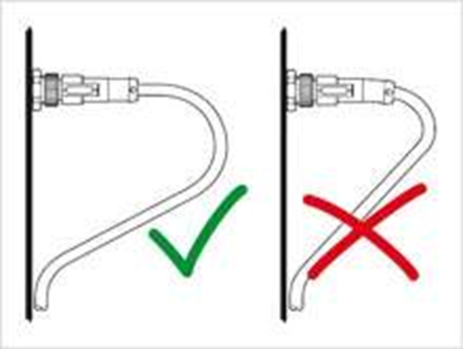
Figure 3. Pulling tension on cables.
1.3 Bend Radius
Consider a bend radius for cables. Fixed installations require a minimum bending radius (R) of five times the diameter (D). A minimum of ten times the diameter (D) is recommended for flexing/moving installations.

Figure 4. Bend Radius for Cables.
1.4 Cables Crush Resistance
To not exceed the cables crush resistance consider:
- Cable ties/clamps should be avoided. Rather than zip ties, use hook and loop fasteners, which must also be applied loosely.

Figure 5. Hook and Loop Fasteners for Cables [2]
- Do not step on or run over cables with vehicles or equipment.
- Be aware of other areas that may constrict cables or conductors and put them at risk of damage.
- Communications cables should not be stapled with standard staples, which may crush them. Use cable staples of the correct size.
1.5 Temperatures Rating for Cables
Especially for installations in harsh environments, with high temperatures, cables in possible contact with fluids, or outdoor applications, consider a cable sheath material capable to handle the temperature rating.
Standard sensor cables supplied by Rheonics have a temperature rating of -30°C to 90°C. For different requirements, user needs to notify it in the RFQ (Request for Quotation).
1.6 Cables Gauge Connected to the SME
- Cables connected to the SME’s terminal blocks should be at maximum 16 AWG, minimum 24 AWG (0.2–1.5 mm²) [3], [4]. The Rheonics sensor cable itself uses 0.25 mm² (about AWG 24) conductors [5].
- It is also recommended to use crimpers or ferrule terminals, with the same AWG size, at the end of the wires connected to the SME. Don’t insert more than two wires in the SME’s terminals and preferably use a double cord terminal or ferrule in those cases. It is always also good to use the correct tools to strip cables and crimp wires.
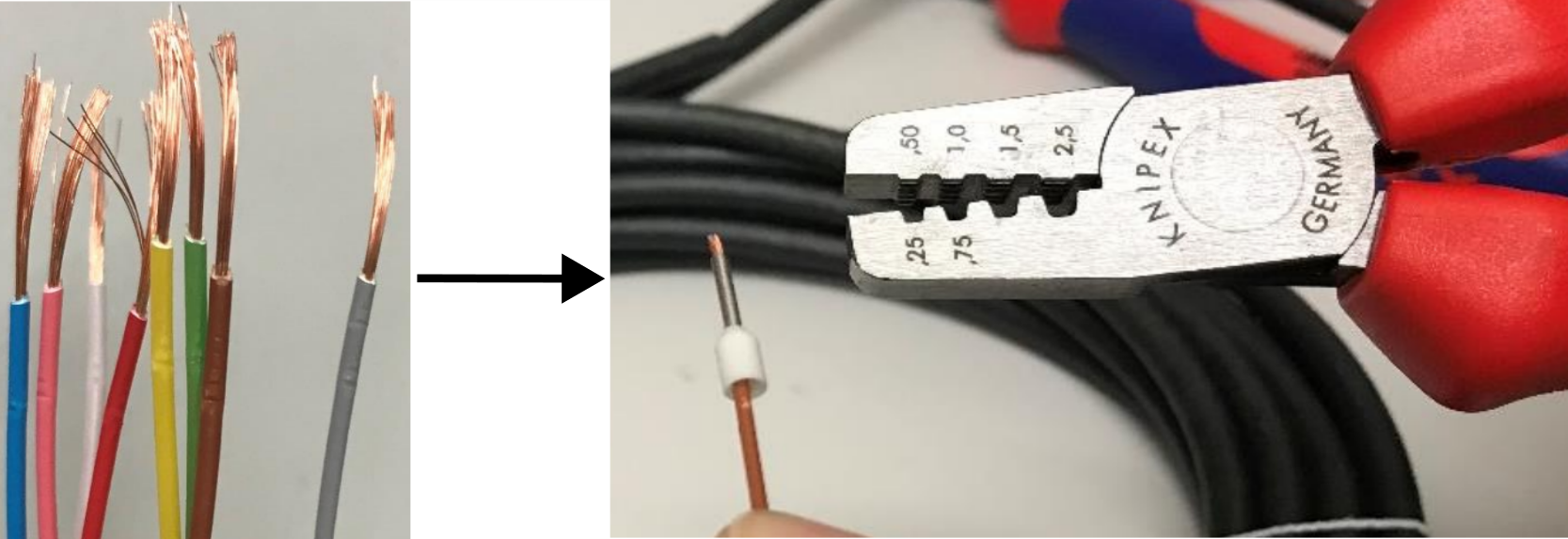
Figure 6. Crimper for Wires.
1.7 Cable Sheath Properties
The cable’s sheath should be selected based on the installation place, liquids cables are exposed to, etc. Table 1 shows the principal sheath materials for industrial applications:
| PUR | TPE | PVC |
|---|---|---|
Polyurethane
| Thermo-Plastic-Elastomer
| Polyvinylchloride
|
Table 1. Principal sheath materials for industrial applications.
2. Cables Involved in a Typical Rheonics SME Installation
The SME-DRM has three terminal blocks involved in a typical installation: block 1 for power, block 2 for the 4-20mA outputs and block 3 for the sensor cable (Figure 7).

Figure 7. SME-DRM Terminal Blocks.
2.1 Power Cable
Positive and negative terminals are connected to the SME through push-in terminal block 1.
DC or AC Power Cables can be single or multi-core cables, depending on the need of flexibility, space available and amount of devices to supply voltage.
Power cables, AC voltage especially, must have a considerable distance from signal, control and communication cables, around 50mm minimum. When using wire ducts inside an electric panel, power and signal cables are recommended to go through different paths, even if they go to the same device.
Specifications for the Power Supply can be found in the article: Powering the Sensor - Input power to transmitter
2.2 Analog Signal Cables
The SME has 3 non-isolated 4-20mA output channels, placed in terminal block 2. For these outputs, use stranded, shielded, twisted-pair wires of 18 to 22 AWG.
Selecting a good cable here is important to ensure a "clean" signal to make its way from the SME to the PLC or analog reader.
- Always use stranded wires (ideally with ferrules or crimpers on the tip). These wires offer good flexibility and bendability, making the installation easier and cleaner.
- Correct Gauge for the SME's Analog Signal can vary between 18, 20 and 22AWG. Consider that 4-20mA signals are affected by a harsh environment and the length of the cable. The thicker the wire (the lower the AWG number), the lower the resistance and signal loss, but the harder the cable is to handle.
- To face the harsh environments of industries, shielded cables are needed for these signals. This shield is a metallic armour that prevents electromagnetic fields, created by the flow through the wires, to come out of the cable and avoids other fields to reach the wires inside the cable. Depending on the level of noise, the shielding options (ordered from low to higher protection) can vary from: Foil Shield, Braid Shield and both at the same time.
- Twisted wires (wires wrapped around each other) are also a useful characteristic that creates electromagnetic compatibility (EMC) between wires of the same circuit and can reduce magnetic noise coming from mechanic or electric devices.
More on good installation of wires in the SME: Connecting Sensor Cables and Wires to Rheonics SME Electronics
Important considerations when reading 4-20mA signals from the SME can be found on the Article: What can go wrong with 4 - 20mA loops ?

Figure 8. Shielded Cables [6]
2.3 Ethernet Cable
Ethernet cables with RJ45 connectors can be used for multiple communication protocols with the SME and another device (e.g. PLC, PC, etc.). When using it, consider a minimum bending radius of 25mm. Depending on the length of the connector itself, the minimum distance “n” in the next drawing may vary but should be close to 70mm.
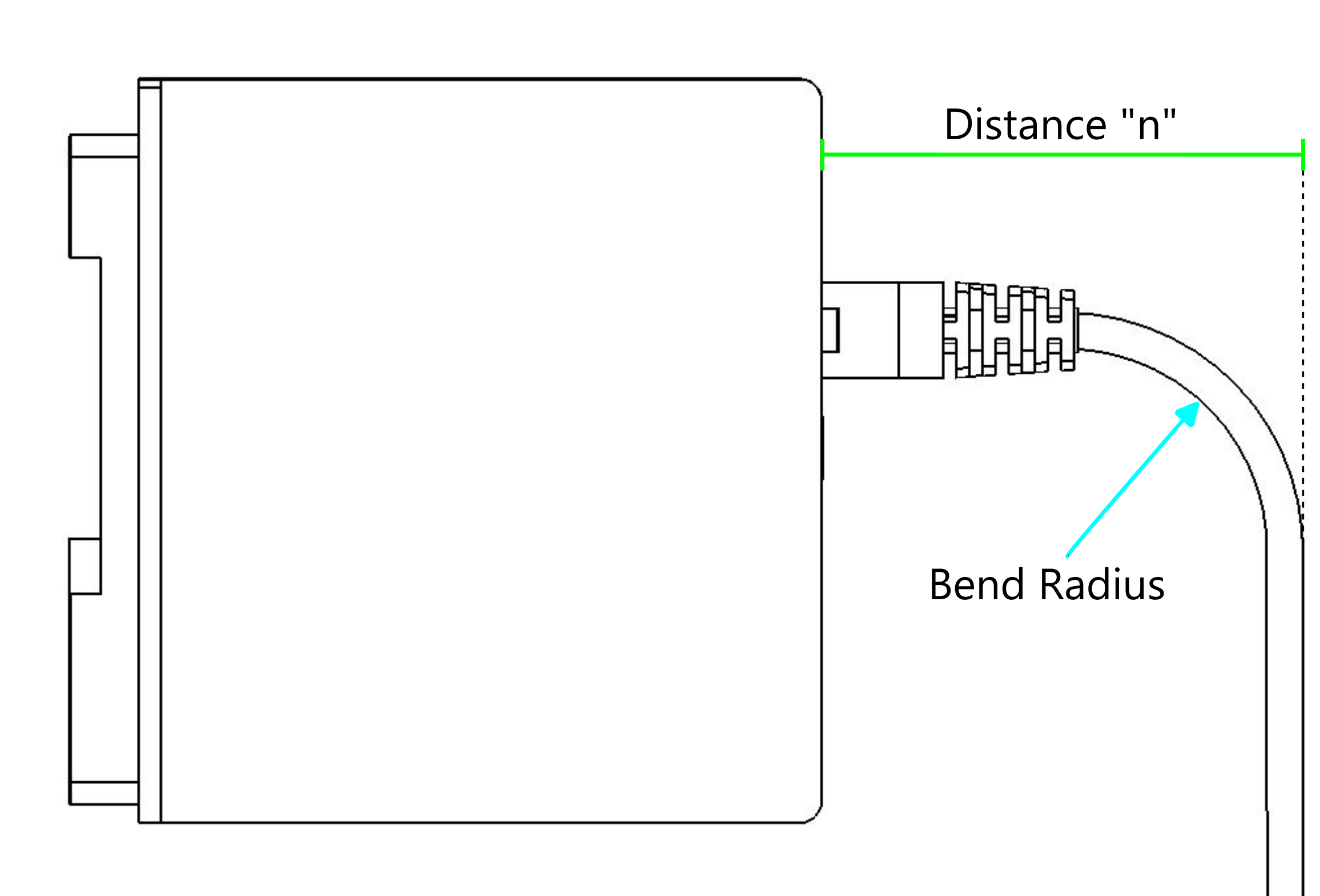
Figure 9. Ethernet Cable
SME’s ethernet connection should go to an Ethernet switch where other devices can be connected to create a network.
Further information about ethernet cable on the SME can be found here: Introducing Ethernet connections on SME
2.4 Sensor Cable
Sensor cable is included when a Rheonics sensor is purchased. It has, in one end, a M12 8-Pin-Female connector that should be inserted into the M12 8-Pin-Male connector of the Sensor. While in the other end, it has 8 stranded wires crimped with white ferrules, that should be placed in the Block Terminal 3 of the SME in a specific order by the colors, see article: Connecting sensor cable to electronics (SME)
Sheath’s material, cable length and connection orientation (180° straight or 90° angled) are customizable when doing a purchase.

Figure 10. M12 180° (Straight) Connector [7]

Figure 11. M12 90° Connector [8]
2.5 USB Cable
The SME’s micro USB Port is used to connect the electronics to a PC and use the Rheonics Control Panel Software to see online data, calibration, historic files, etc. Related articles are:
- Introducing USB connections on the Rheonics SME (sensor electronics)
- Nothing is happening when I plug in the USB cable!
DISCLAIMER |
3. References
- Rheonics GmbH, Rheonics SRV Inline Viscometer Manual, DocID SRV-G1-OP-2606, Jun. 2026.
- Accu-Tech, "Accu-Tech." [Online]. Available: https://www.accu-tech.com/. [Accessed: Sep. 23, 2026].
- Rheonics, "Wire preparation for SME-DRM (Din Rail Mount)," Rheonics Support. [Online]. Available: https://support.rheonics.com/en/support/solutions/articles/81000408391. [Accessed: Sep. 23, 2026].
- Rheonics, "Wire preparation for SME-TR/TRD (Outdoor Mount)," Rheonics Support. [Online]. Available: https://support.rheonics.com/en/support/solutions/articles/81000410179. [Accessed: Sep. 23, 2026].
- Rheonics, "Standard sensor cable - with straight M12 connector," datasheet. [Online]. Available: https://rheonics.com/wp-content/uploads/2025/02/180o_Straight_Standard-Cable-STD.pdf. [Accessed: Sep. 27, 2026].
- Cables RCT, "Fabricante de cables de baja tensión - Cables RCT." [Online]. Available: https://www.cablesrct.com/. [Accessed: Sep. 23, 2026].
- Murrelektronik, "We are experts in automation solutions | Murrelektronik." [Online]. Available: https://www.murrelektronik.com/. [Accessed: Sep. 23, 2026].
- Belden, "Lumberg Automation." [Online]. Available: https://www.belden.com/about/connected-brands/lumberg-automation. [Accessed: Sep. 27, 2026].