What products are involved?
This article is based on using Rheonics Sensor Module Electronics (SME), SenseCAP M2 LoRaWAN gateway, and the HD67D03-B2 LoRaWAN/Modbus TCP Master Converter (868 MHz)
What is the purpose of this article?
This article describes the process of integrating Rheonics sensors with the HD67D03-B2 868MHz converter and the SenseCAP M2, so data can be transmitted wirelessly and visualized remotely via The Things Network.
TABLE OF CONTENTS
1. Overview
LoRaWAN is a long-range, low-power communication protocol designed for transmitting sensor data over wide areas. In this article, the HD67D03-B2 converts data from the SME via Modbus TCP and converts it into LoRaWAN messages. These messages are then sent to the SenseCAP M2 gateway, which is connected to the Internet and sends the data to The Things Network (TTN) or other LoRaWAN network servers. TTN is a LoRaWAN ecosystem that includes The Things Stack (TTS), a LoRaWAN network server that enables remote data access. Once received, the data can be decoded and can be visualized remotely.
Following this setup, Rheonics sensors can transmit sensor values wirelessly and be monitored in real time from anywhere through The Things Stack server.
 Figure 1: Architecture of Rheonics SME, HD67D03-B2, SenseCAP M2, and The Things Network integration
To configure the SenseCAP M2 LoRaWAN gateway refer to the following article Configuring LoRaWAN Gateway for Remote Data Visualization of Rheonics Sensors2. HD67D03-B2 868MHz Configuration
The HD67D03-B2 868MHz configuration needs to be done in The Things Stack and using the SW67D03 software.
2.1. Configuration in The Things Stack (TTS)
1. Enter The Things Network Console and access the account.
2. Select Create application.
 Figure 2: Application creation
3. Add a name and ID for the new application.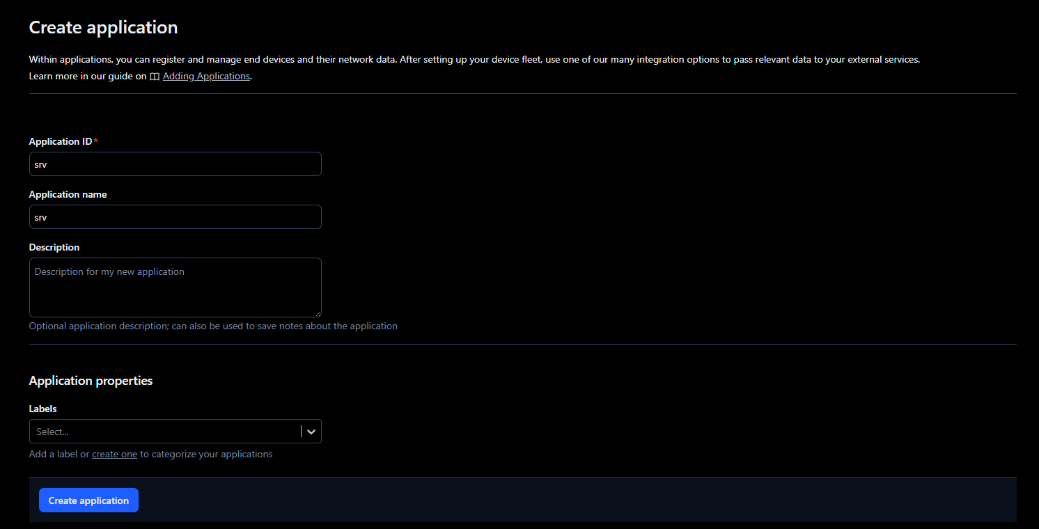
4. Next, go to the application, select End devices, and click on Register end device.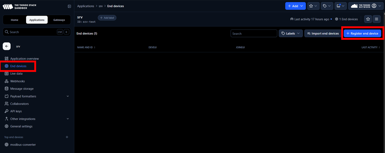
5. Register the end device with the following parameters
- Frequency plan: Select a frequency plan that matches the one specified in both the device and the SenseCAP M2 to ensure compatibility. In this case, Europe 863-870 MHz (SF9 for RX2 - recommended)
- LoRaWAN version: LoRaWAN Specification 1.0.1

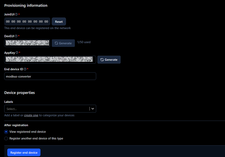
6. In the Provisioning information section, fill with the following and click on Register end device.
- JoinEUI: e.g. 00 00 00 00 00 00 00 00 - This identifies the Join Server, which handles the initial communication between the end device and TTS. It is usually assigned by the device manufacturer, but it can also be set by the user. If no JoinEUI is provided, a value of all zeros can be used if the Join Server supports it. It is possible to use the same JoinEUI for different end devices, but the DevEUI should be unique per end device.
- DevEUI: from HD67D03-B2 label
- AppKey: generate a random key (necessary for the HD67D03-B2 to be able to connect to TTS)
- End device ID: e.g. modbus-converter
2.2. Configure HD67D03-B2 with SW67D03 software
1. Download the HD67D03-B2 software that can be found in SW67D03 software
2. Connect the HD67D03-B2 through Ethernet to a PC as shown in the following diagram.
3. Open the HD67D03-B2 software, which is under the name Compositor SW67D03.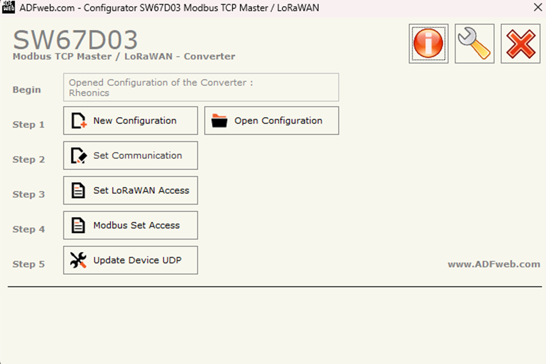
Figure 8: Compositor SW67D03 software
4. Choose New Configuration and select a name for the configuration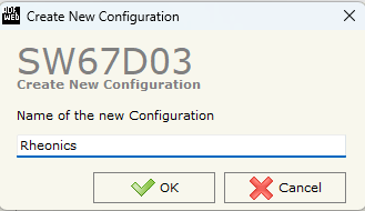
5. Select Set Communication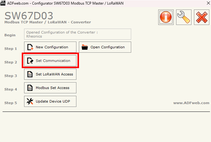
6. Fill the following spaces:
- Ethernet Connection
- Device name: viscometer
- LoRaWAN
- RF Band: EU868 (needs to be the same as the one assigned in the SenseCapM2 and TTS)
- Network Type: Public
- Adaptive DataRate: ✅
- DataRate: 3 -LoRa: SF9/125kHz 1760 [bit/s] (make sure it is the same as in the Frequency Plan selected in TTS)
- Transmission Type: Confirmed
- Max Payload Size: 115
- JoinEUI: 00 00 00 00 00 00 00 00 (Same JoinEUI as in the TTS end device creation)
- Activation Method: Over-the-Air Activation (OTAA)
- Application Key: Same AppKey generated in TTS end device creation
- Port Field: Fixed
- LNCHECK every xx min: 5
- Modbus TCP Master
- IP Address: 192.168.100.63 (The IP that is assigned to the HD67D03-B2 and used for uploading its configuration)
- SubNet Mask: 255.255.255.0
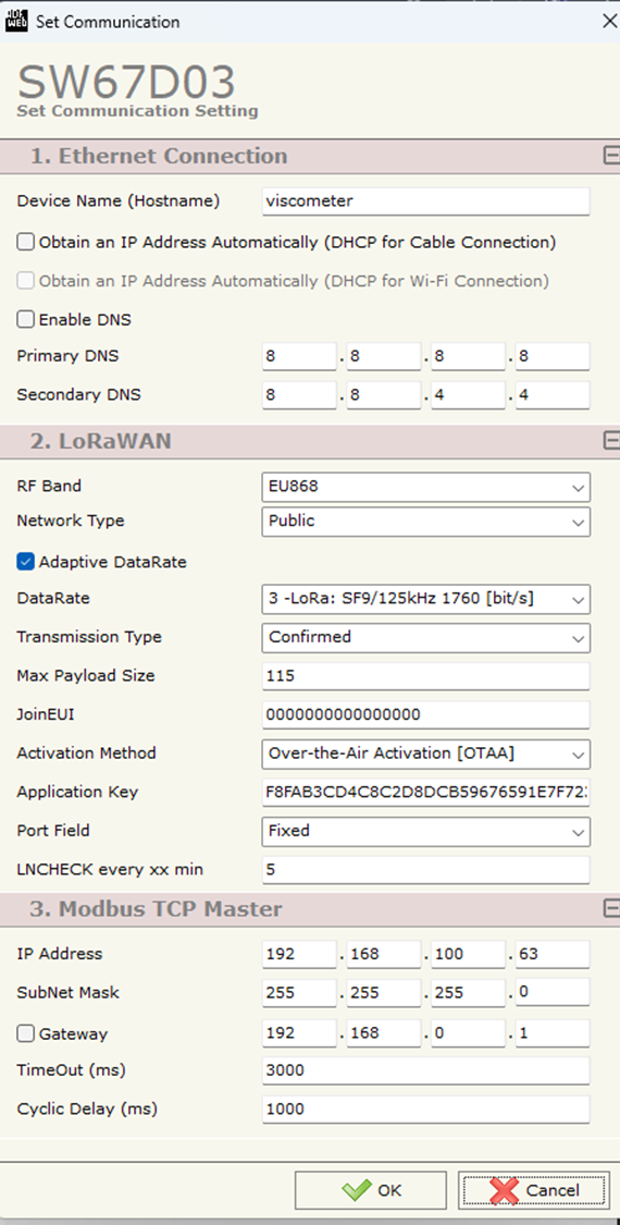
Figure 11: Set Communication - Configuration
7. Select Set LoRaWAN Access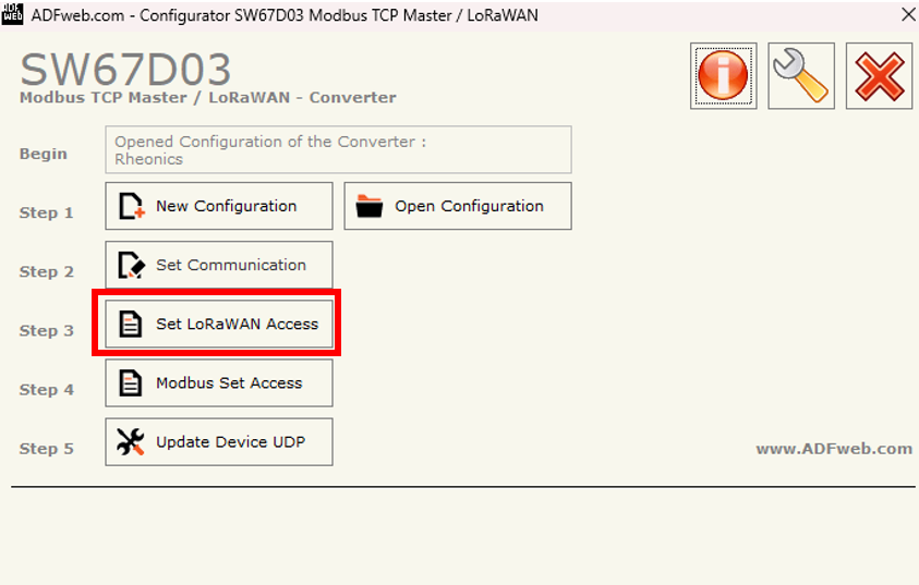
Figure 12: Set LoRaWAN Access
8. Fill the spaces as follows
- Start Byte: 1 - Position in the device’s internal memory where data reading begins.
- Num. Byte: 113 - Number of consecutive bytes of data to read starting from the Start Byte.
- On Timer: ✅ - Enables sending the messages cyclically
- Time(s): 30 - Sends messages every 30 seconds (or according to the interval specified).
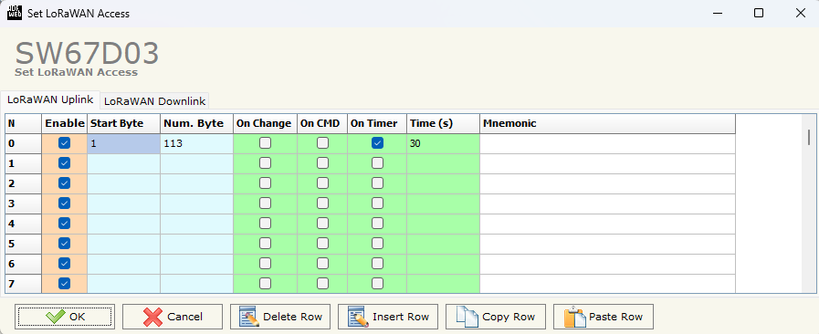
Figure 13: Set LoRaWAN Access - Configuration
9. Select Modbus Set Access
Figure 14: Modbus Set Access
10. The following table should be completed as follows to read the 23 parameters from Rheonics SME
- SlaveIP Address: IP of the SME
- Port: 502 (default)
- Slave ID: 255
- Type: Input Register
- Address: Address of Modbus TCP Input Registers
- NPoint: 2 - Number of consecutive registers to be read
- Poll Time: 3000 ms
- Position: Minimum position is 1, because the first byte is ignored. Between each position should be 4 bytes.

Figure 15: Modbus Set Access - Configuration
11. SW67D03 software does not allow Slave ID = 255. For this reason, open the folder of the software and search for the project created.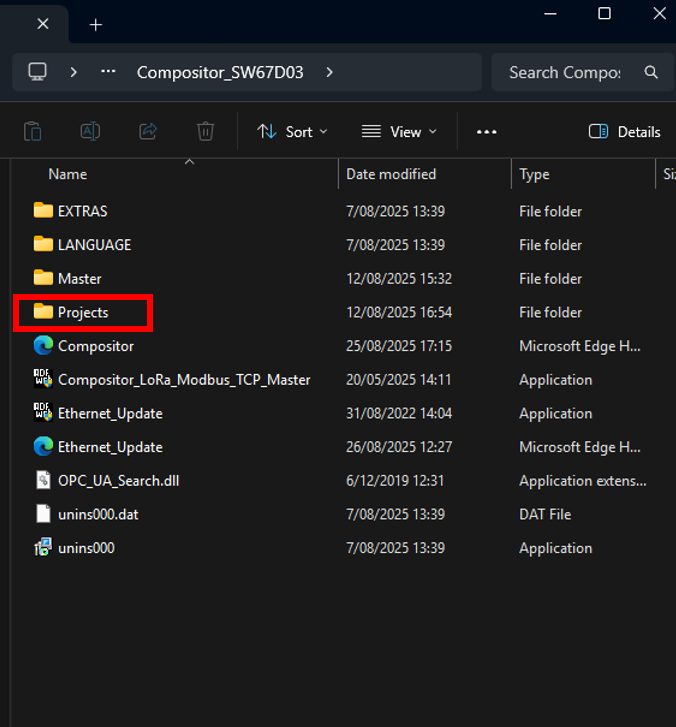
Figure 16: Projects folder
12. In this case, the project is in Projects>>Rheonics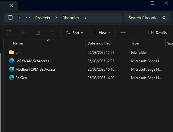
Figure 17: Rheonics projects folder
13. Open the ModbusTCPM_SetAccess file and paste the following to write the 23 parameters and save the file.
<PROFINET_Master_to_Modbus_TCP_Master><Modbus_Read><row Enable="Y" IP_Address="192.168.100.62" Port="502" Slave_ID="255" Type="Input Register" Address="40" NPoint="2" PollTime="3000" MaxError="0" Position="1" Bit="0" Swap="" SwapWord="" Index_Topic="-1" Mnemonic=""/><row Enable="Y" IP_Address="192.168.100.62" Port="502" Slave_ID="255" Type="Input Register" Address="48" NPoint="2" PollTime="3000" MaxError="0" Position="5" Bit="0" Swap="" SwapWord="" Index_Topic="-1" Mnemonic=""/><row Enable="Y" IP_Address="192.168.100.62" Port="502" Slave_ID="255" Type="Input Register" Address="56" NPoint="2" PollTime="3000" MaxError="0" Position="9" Bit="0" Swap="" SwapWord="" Index_Topic="-1" Mnemonic=""/><row Enable="Y" IP_Address="192.168.100.62" Port="502" Slave_ID="255" Type="Input Register" Address="64" NPoint="2" PollTime="3000" MaxError="0" Position="13" Bit="0" Swap="" SwapWord="" Index_Topic="-1" Mnemonic=""/><row Enable="Y" IP_Address="192.168.100.62" Port="502" Slave_ID="255" Type="Input Register" Address="72" NPoint="2" PollTime="3000" MaxError="0" Position="17" Bit="0" Swap="" SwapWord="" Index_Topic="-1" Mnemonic=""/><row Enable="Y" IP_Address="192.168.100.62" Port="502" Slave_ID="255" Type="Input Register" Address="80" NPoint="2" PollTime="3000" MaxError="0" Position="21" Bit="0" Swap="" SwapWord="" Index_Topic="-1" Mnemonic=""/><row Enable="Y" IP_Address="192.168.100.62" Port="502" Slave_ID="255" Type="Input Register" Address="88" NPoint="2" PollTime="3000" MaxError="0" Position="25" Bit="0" Swap="" SwapWord="" Index_Topic="-1" Mnemonic=""/><row Enable="Y" IP_Address="192.168.100.62" Port="502" Slave_ID="255" Type="Input Register" Address="96" NPoint="2" PollTime="3000" MaxError="0" Position="29" Bit="0" Swap="" SwapWord="" Index_Topic="-1" Mnemonic=""/><row Enable="Y" IP_Address="192.168.100.62" Port="502" Slave_ID="255" Type="Input Register" Address="104" NPoint="2" PollTime="3000" MaxError="0" Position="33" Bit="0" Swap="" SwapWord="" Index_Topic="-1" Mnemonic=""/><row Enable="Y" IP_Address="192.168.100.62" Port="502" Slave_ID="255" Type="Input Register" Address="112" NPoint="2" PollTime="3000" MaxError="0" Position="37" Bit="0" Swap="" SwapWord="" Index_Topic="-1" Mnemonic=""/><row Enable="Y" IP_Address="192.168.100.62" Port="502" Slave_ID="255" Type="Input Register" Address="120" NPoint="2" PollTime="3000" MaxError="0" Position="41" Bit="0" Swap="" SwapWord="" Index_Topic="-1" Mnemonic=""/><row Enable="Y" IP_Address="192.168.100.62" Port="502" Slave_ID="255" Type="Input Register" Address="128" NPoint="2" PollTime="3000" MaxError="0" Position="45" Bit="0" Swap="" SwapWord="" Index_Topic="-1" Mnemonic=""/><row Enable="Y" IP_Address="192.168.100.62" Port="502" Slave_ID="255" Type="Input Register" Address="136" NPoint="2" PollTime="3000" MaxError="0" Position="49" Bit="0" Swap="" SwapWord="" Index_Topic="-1" Mnemonic=""/><row Enable="Y" IP_Address="192.168.100.62" Port="502" Slave_ID="255" Type="Input Register" Address="144" NPoint="2" PollTime="3000" MaxError="0" Position="53" Bit="0" Swap="" SwapWord="" Index_Topic="-1" Mnemonic=""/><row Enable="Y" IP_Address="192.168.100.62" Port="502" Slave_ID="255" Type="Input Register" Address="152" NPoint="2" PollTime="3000" MaxError="0" Position="57" Bit="0" Swap="" SwapWord="" Index_Topic="-1" Mnemonic=""/><row Enable="Y" IP_Address="192.168.100.62" Port="502" Slave_ID="255" Type="Input Register" Address="160" NPoint="2" PollTime="3000" MaxError="0" Position="61" Bit="0" Swap="" SwapWord="" Index_Topic="-1" Mnemonic=""/><row Enable="Y" IP_Address="192.168.100.62" Port="502" Slave_ID="255" Type="Input Register" Address="168" NPoint="2" PollTime="3000" MaxError="0" Position="65" Bit="0" Swap="" SwapWord="" Index_Topic="-1" Mnemonic=""/><row Enable="Y" IP_Address="192.168.100.62" Port="502" Slave_ID="255" Type="Input Register" Address="176" NPoint="2" PollTime="3000" MaxError="0" Position="69" Bit="0" Swap="" SwapWord="" Index_Topic="-1" Mnemonic=""/><row Enable="Y" IP_Address="192.168.100.62" Port="502" Slave_ID="255" Type="Input Register" Address="184" NPoint="2" PollTime="3000" MaxError="0" Position="73" Bit="0" Swap="" SwapWord="" Index_Topic="-1" Mnemonic=""/><row Enable="Y" IP_Address="192.168.100.62" Port="502" Slave_ID="255" Type="Input Register" Address="192" NPoint="2" PollTime="3000" MaxError="0" Position="77" Bit="0" Swap="" SwapWord="" Index_Topic="-1" Mnemonic=""/><row Enable="Y" IP_Address="192.168.100.62" Port="502" Slave_ID="255" Type="Input Register" Address="200" NPoint="2" PollTime="3000" MaxError="0" Position="81" Bit="0" Swap="" SwapWord="" Index_Topic="-1" Mnemonic=""/><row Enable="Y" IP_Address="192.168.100.62" Port="502" Slave_ID="255" Type="Input Register" Address="208" NPoint="2" PollTime="3000" MaxError="0" Position="85" Bit="0" Swap="" SwapWord="" Index_Topic="-1" Mnemonic=""/><row Enable="Y" IP_Address="192.168.100.62" Port="502" Slave_ID="255" Type="Input Register" Address="216" NPoint="2" PollTime="3000" MaxError="0" Position="89" Bit="0" Swap="" SwapWord="" Index_Topic="-1" Mnemonic=""/></Modbus_Read><Modbus_Write/></PROFINET_Master_to_Modbus_TCP_Master><!--SW_VERSION = 1.007--> |
14. If the IP of the HD67D03-B2 is known, click on Update Device UDP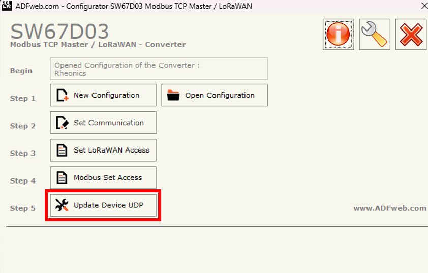
Figure 18: Update Device UDP
15. Insert the known IP, select configuration, and Execute Update Firmware.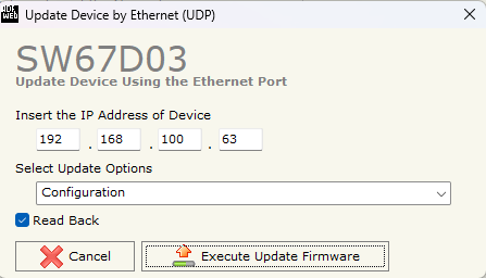
Figure 19: Execute Update Firmware
16. An Ok message should appear.
Figure 20: Ok message confirmation
17. If the IP of the device is unknown, turn OFF the device, and put Dip1 of Dip-Switch of the device in ON position. Turn on the device, connect the Ethernet cable to the PC, and insert the IP “192.168.2.205”.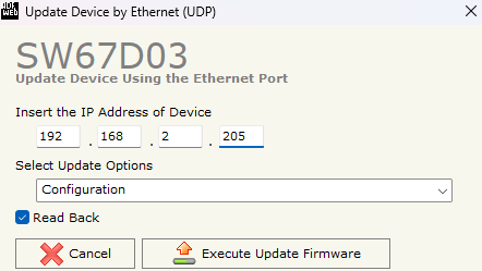
Figure 21: Update Device by Ethernet with default IP
18. After the Ok message appears, turn OFF the device.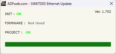
19. Put Dip1 of Dip-Switch A in OFF position and turn ON the device. The device can now be configured using the IP chosen in Set Communication configuration.
20. Connect the HD67D03 to the SME as the following diagram.

Figure 23: HD67D03 Connection with SME
3. Sensor data visualization
1. Enter the TTS server URL, and click on the end-device.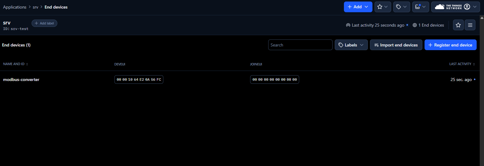
Figure 24: HD67D03 Connection with SME
2. Select the Payload formatters Tab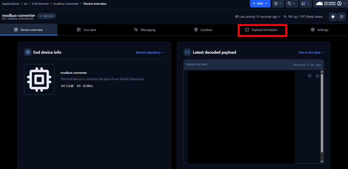
Figure 25: Payload formatters
3. On Setup, select the following
- Formatter type: Custom JavaScript formatter
- Formatter code: Paste the following code to transform the data received into numbers for easy visualization.
function decodeUplink(input) { let bytes = input.bytes.slice(2); let data = {}; const parameterNames = [ "viscosity_median", // Parameter 0 "density_median", // Parameter 1 "temperature_median", // Parameter 2 "kinematic_viscosity", // Parameter 3 "density_average", // Parameter 4 "viscosity_raw", // Parameter 5 "density_raw", // Parameter 6 "temperature_raw", // Parameter 7 "resonant_frequency", // Parameter 8 "compensated_resonant_frequency", // Parameter 9 "damping_frequency", // Parameter 10 "coil_temperature", // Parameter 11 "viscosity_last_good", // Parameter 12 "density_last_good", // Parameter 13 "modbus_512_display", // Parameter 14 "modbus_514_display", // Parameter 15 "modbus_516_display", // Parameter 16 "estimated_temperature", // Parameter 17 "temperature_PT1000", // Parameter 18 "viscosity_model_calc", // Parameter 19 "density_model_calc", // Parameter 20 "concentration_model_calc", // Parameter 21 "sensor_cleanliness_ratio" // Parameter 22 ]; function bytesToFloat32(byteArray) { let buffer = new ArrayBuffer(4); let view = new DataView(buffer); byteArray.forEach((b, i) => view.setUint8(i, b)); return view.getFloat32(0, false); } for (let i = 0; i < bytes.length; i += 4) { if (i / 4 < parameterNames.length) { let paramName = parameterNames[i / 4]; let floatValue = bytesToFloat32(bytes.slice(i, i + 4)); data[paramName] = isNaN(floatValue) ? "NaN" : parseFloat(floatValue.toFixed(6)); } } return { data: data, warnings: [], errors: [] }; } |

Figure 26: Code in Payload formatters section
4. Select Live Data Tab to visualize the parameters obtained from Rheonics SME.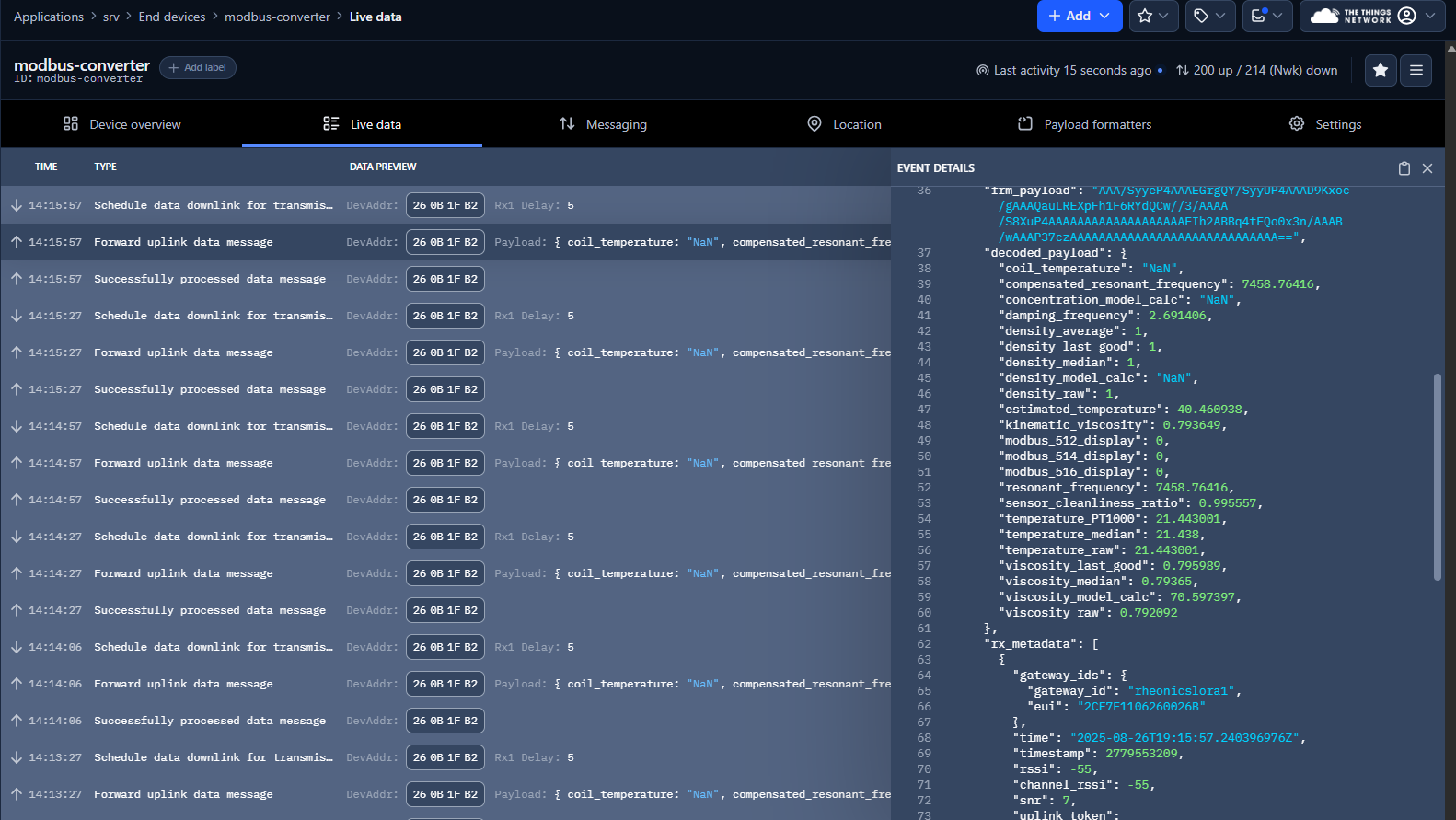
Figure 27: Live Data Tab