
What products are involved?The SME-DRM, the DIN rail mount housing of the Rheonics sensor module electronics. It is used with the SRV viscometer and the SRD density meter. What is the purpose of this article?To give the cabinet layout dimensions for an SME-DRM before the hardware arrives, and the mounting steps once it does. |
Table of Contents
- 1. Overview
- 2. Prerequisites
- 3. SME-DRM Dimensions
- 4. Mounting the SME-DRM on the Rail
- 5. Cabinet Requirements
- 6. Sizing the Power Supply
- 7. Grounding and Bonding
- 8. Routing Cables Inside the Cabinet
- 9. References
1. Overview
The SME is the module electronics of a Rheonics sensor. It reads the probe signals, translates them into temperature, viscosity, and density values depending on the sensor, and transmits them over industrial communication protocols. It comes in four housings:
- SME-TRD (E1): coated aluminium, IP66 and IP68, for outdoors, with a local display.
- SME-TR (E2): the same, without the display.
- SME-DRM (E3): stainless steel, IP20, for a 35 mm DIN rail inside a cabinet.
- SME-BOX (E4): a tabletop unit with a built-in touch-panel PC, for the lab.
The SME-TR and SME-TRD mount outside a cabinet and are grounded differently, so what follows applies to the SME-DRM only.
The SME-DRM takes 44.6 mm of 35 mm DIN rail and needs 20.4 mm above the rail, 29.6 mm below it, and 86 mm of depth from the back of the housing. The rail is not centered on the housing.
Warning: For hazardous areas, see Enclosure for Sensor electronics and Zener barriers. Each Ex sensor is supplied with its own user manual; always check the Ex manual that comes with the sensor. |
2. Prerequisites
- The SME-DRM delivered with your probe.
- A 35 mm DIN rail to IEC 60715 in the cabinet, bonded to the cabinet's grounding system.
- A 24 V DC supply sized as in section 6. See Powering the Sensor - Input power to transmitter.
- The sensor cable supplied with the sensor, and a screwdriver for the terminals. See Connecting Sensor Cables and Wires to Rheonics SME Electronics.
Each SME is factory-paired with one sensor probe and must only be used with that probe. To connect it to a different probe, contact Rheonics Support at support@rheonics.com. |
3. SME-DRM Dimensions
3.1. Housing Size and Ratings
Installed orientation, with the rail horizontal and the terminals facing you.
| Dimension | Value |
|---|---|
| Height, across the rail | 85 mm |
| Width, along the rail | 44.6 mm |
| Depth, overall | 86 mm |
| Weight | 0.2 kg (0.4 lb) |
| Casing material | Stainless Steel 304 (1.4301) |
| Protection rating | IP20 |
Table 1. SME-DRM dimensions and ratings.
The rail is not centered on the SME-DRM: the housing extends 20.4 mm above the rail and 29.6 mm below it (Figure 1). The spring latch at the bottom of the DIN rail clip holds the rail against the fixed hook at the top.
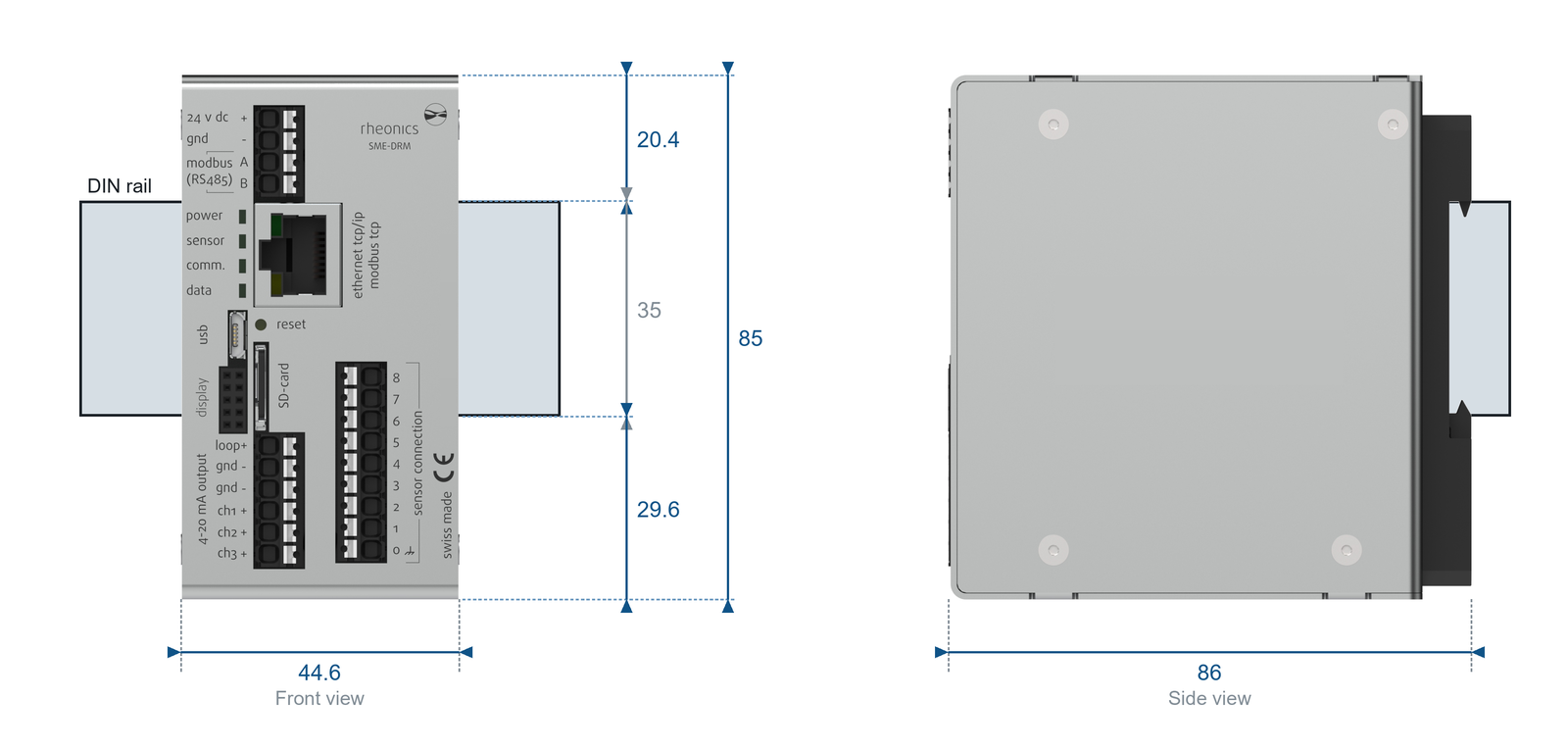
Figure 1. SME-DRM dimensions and the space to leave around the rail.
For a cabinet layout, download the drawing and the CAD models (Table 2). Rheonics sensor electronics SME Drawings and 3D Models has them for every SME housing.
| File | Link |
|---|---|
| SME-DRM drawing, rev. A (PDF) | Download |
| SME-DRM CAD models, DXF and STEP (ZIP) | Download |
Table 2. SME-DRM drawing and CAD models.
3.2. Minimum Space to Leave Around the Rail
Leave at least this much space around the rail (Figure 1). Rheonics does not specify a gap between adjacent units, so allow 44.6 mm of rail per unit plus any spacing you leave.
| Direction | Minimum space |
|---|---|
| Above the top edge of the rail | 20.4 mm |
| Below the bottom edge of the rail | 29.6 mm |
| Along the rail, per unit | 44.6 mm |
| In front of the housing back face | 86 mm |
Table 3. SME-DRM mounting clearances around the rail.
The 86 mm depth is measured from the back of the housing. The SME-DRM fits 35 mm rails that are 7.5 mm or 15 mm deep; add the rail depth to get the total depth from the mounting plate. |
4. Mounting the SME-DRM on the Rail
- Switch off and isolate the cabinet supply.
- Check that there is enough free space on and around the rail for the housing (Table 3).
- Find the DIN rail clip on the back of the housing (Figure 2): a fixed hook at the top and a spring latch at the bottom.
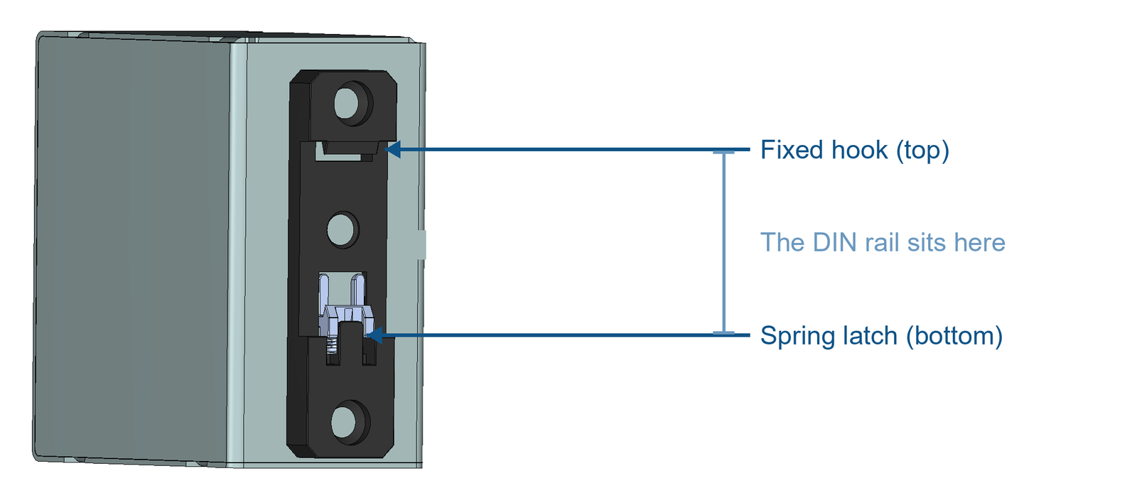
Figure 2. Back of the SME-DRM: fixed hook at the top, spring latch at the bottom.
- Press the bottom of the clip against the lower edge of the rail, push the housing up, and latch the upper edge of the clip over the top edge of the rail (Figure 3).
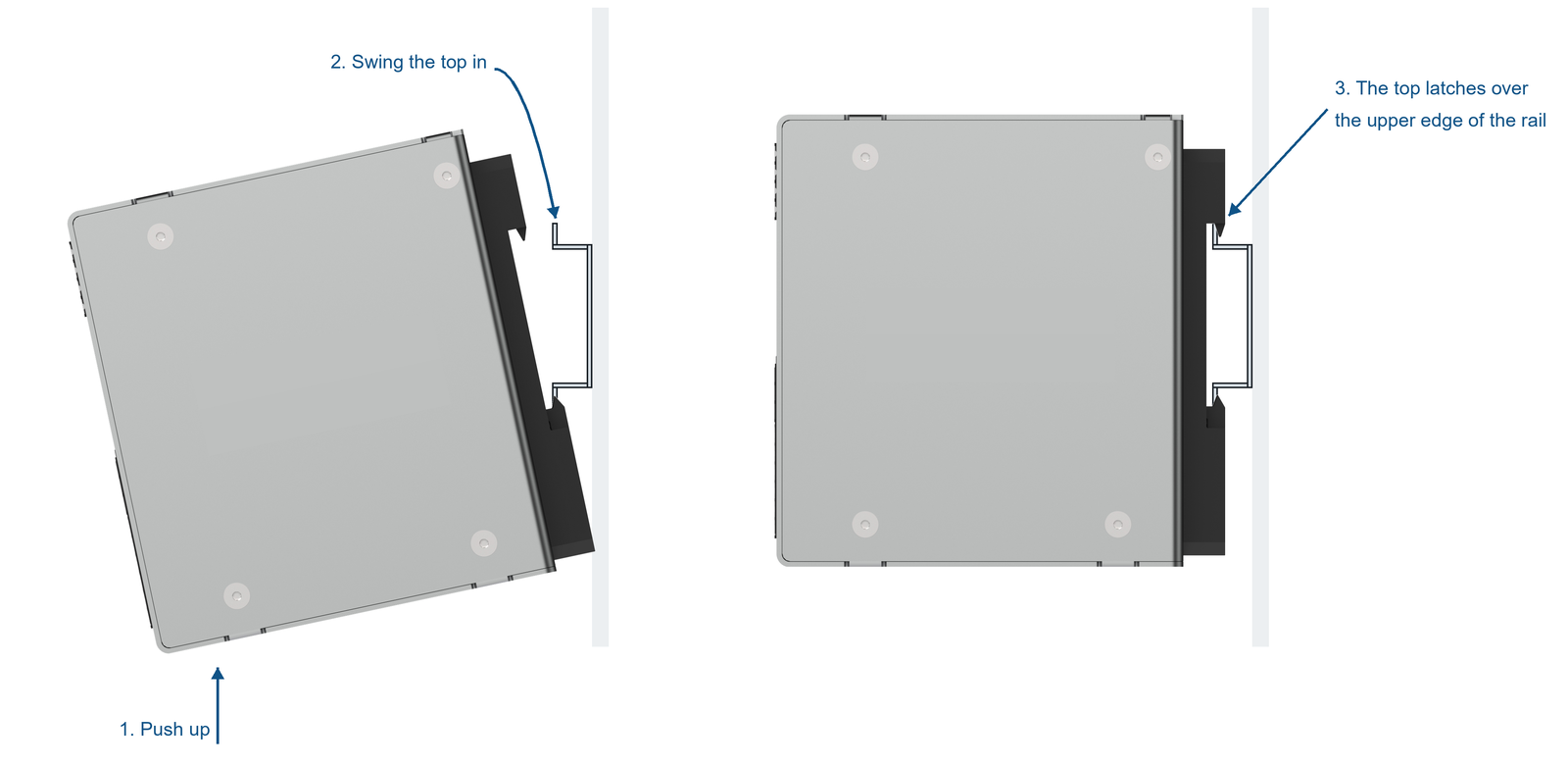
Figure 3. Mounting the SME-DRM on the rail.
- Try to lift and rock the housing. A seated unit does not move.
Wiring comes after mounting. See Wire preparation for SME-DRM (Din Rail Mount) and Connecting Sensor Cables and Wires to Rheonics SME Electronics.
5. Cabinet Requirements
The SME-DRM is rated IP20, so the cabinet carries the ingress protection and the cabinet rating must match the environment.
The SME-DRM operates from -20 to +65 °C, stores from -40 to +85 °C, and takes 0 to 95% humidity non-condensing up to 5000 m. Standard sensor cables are rated -30 °C to 90 °C, so the SME-DRM, not the cable, sets the temperature limit inside the cabinet. The unit consumes at most 5 W, so it adds little heat.
6. Sizing the Power Supply
From the SRV and SRD Operator Manuals:
| Per unit | Voltage | Current | Power |
|---|---|---|---|
| SME-DRM draws | 24 V DC nominal, 18 to 36 V DC accepted | at most 200 mA | at most 5 W |
| Size the supply for | at least 400 mA | at least 10 W | |
| Fuse, where required | slow-blow above 500 mA |
Table 4. SME-DRM power supply.
Use a certified supply, free of significant noise. Powering the Sensor - Input power to transmitter gives supply examples.
Warning: Avoid ground loops. They can drive excessive current on the return wire of the 24 V supply and permanently damage the unit. Power the SME from a separate 24 V supply with galvanic separation. |
7. Grounding and Bonding
Bond all metallic components inside the cabinet, mounting plates and DIN rails and cable trays included, to the cabinet's grounding system to form one equipotential zone. Bond the rail before you populate it. Protective earth and signal grounding are separate requirements; see sec. 11.8 of the SRV or SRD Operator Manual.
The correct grounding of the electronics is set by the wiring variant, which is marked on the housing: an SME-DRM takes variant A or B, chosen by probe type. Variants C and D route grounding through an in-housing terminal that only the SME-TR and SME-TRD have. See Wire preparation for SME-DRM (Din Rail Mount) for the grounding cable, and Mitigating EMI impact on Rheonics sensors for the signal side.
Figure 4 shows variants A and B wired on a DIN rail, as in the operator manual.
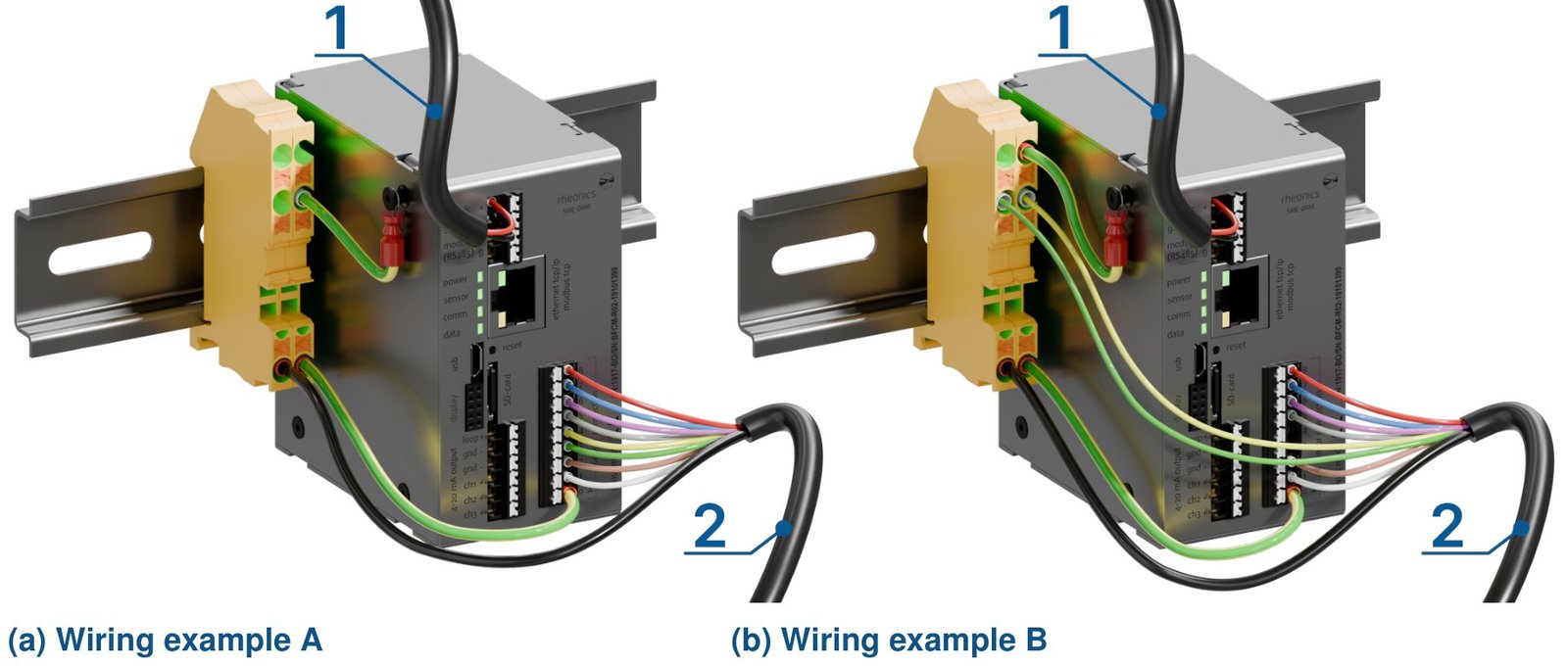
Figure 4. SME-DRM wiring examples, Variant A (left) and Variant B (right): 1 power (24V DC), 2 sensor cable.
8. Routing Cables Inside the Cabinet
Keep at least 50 mm between power cables and control or signal cables, and run them on separate paths even where they end at the same device. Keep signal cables at least 200 mm from high-power cables and VFDs.
The supply and Modbus terminals are at the top of the housing, the 4-20 mA output and the sensor connection at the bottom, so plan the routing around which end each cable leaves.

Figure 5. Terminal groups on the front panel.
Best Practices for Cabling Installation covers wire gauge, ferrules, bend radius, and shielding.
9. References
- Rheonics, "Rheonics SRV Operator Manual," SRV-G1-OP-2606, sec. 5.3, sec. 5.3.2.3, sec. 5.3.3.1, sec. 11 and sec. 11.8.
- Rheonics, "Rheonics SRD Operator Manual," SRD-G1-OP-2606, sec. 5.3.2.3, sec. 5.3.3.1 and sec. 11.8.
- Rheonics, "SME-DRM DIN rail mount sensor electronics," drawing rev. A. [Online]. Available: Rheonics_SME-DRM_A.pdf
- Rheonics, "Rheonics SME-DRM CAD package," DXF and STEP. [Online]. Available: Rheonics_SME-DRM.zip
- Rheonics Support, "Best Practices for Cabling Installation." [Online]. Available: Best Practices for Cabling Installation
- Rheonics Support, "Enclosure for Sensor electronics and Zener barriers." [Online]. Available: Enclosure for Sensor electronics and Zener barriers
- Rheonics Support, "Powering the Sensor - Input power to transmitter." [Online]. Available: Powering the Sensor - Input power to transmitter
- Rheonics Support, "Rheonics sensor electronics SME Drawings and 3D Models." [Online]. Available: Rheonics sensor electronics SME Drawings and 3D Models
- Rheonics Support, "Wire preparation for SME-DRM (Din Rail Mount)." [Online]. Available: Wire preparation for SME-DRM (Din Rail Mount)